CN203025493U - Electrical switching system - Google Patents
Electrical switching system Download PDFInfo
- Publication number
- CN203025493U CN203025493U CN 201220456556 CN201220456556U CN203025493U CN 203025493 U CN203025493 U CN 203025493U CN 201220456556 CN201220456556 CN 201220456556 CN 201220456556 U CN201220456556 U CN 201220456556U CN 203025493 U CN203025493 U CN 203025493U
- Authority
- CN
- China
- Prior art keywords
- current
- switch spindle
- magnet
- supply line
- electromagnet
- Prior art date
- Legal status (The legal status is an assumption and is not a legal conclusion. Google has not performed a legal analysis and makes no representation as to the accuracy of the status listed.)
- Expired - Fee Related
Links
Images

Abstract
The utility model discloses an electrical switching system. According to the system, the state of electric equipment is determined by detecting the current parameter, and corresponding operation is performed according to the calculation result. The electrical switching system adopts the following technical scheme that the system comprises a circuit switch assembly, a current transformer and an on-off control circuit; wherein the circuit switch assembly is installed in power supply lines for making the power supply lines always remain in the conduction state during the operation of the electric equipment on the power supply lines; the current transformer is installed in the power supply lines, wherein no output current is generated when no current flows through the power supply lines, and during the operation of the electric equipment, the working current on the power supply lines flows through the current transformer, and the output induced current signal of the secondary side of the current transformer is used as the input signal of the on-off control circuit; the on-off control circuit is connected with the current transformer and used to convert the input signal into a working current to make internal circuits operate on one hand, and determine the working condition of the electric equipment on the power supply lines according to the input signal and perform control operation according to the working condition on the other hand.
Description
Technical field
The utility model relates to electric device, relates in particular to electrical switching system.
Background technology
In the modern life, no matter be in the family or during commercial and industrial used, the use of various electrical equipments was more prevalent.A lot of these electrical equipments of time are in holding state, and consume stand-by power consumption.Although compare the normal power of equipment, standby power is usually much smaller, and due to the electrical equipment enormous amount, aggregated duration is long, so the electric energy that accumulative total consumes or considerable.
According to related data, the stand-by power consumption situation in average family is as follows:
Table 1

Source:Meier?&?Lebot?2002.
The proportion of stand-by power consumption in family's total electricity consumption is as follows.
The estimation of table 2 stand-by power consumption

This shows, the existence of stand-by power consumption has caused great energy dissipation, has increased user's electric cost expenditure, has also increased the weight of environmental pressure.
When equipment is in online holding state for a long time, the part components and parts will generate heat, if deal with improperly, the danger that causes fire be arranged; Be in for a long time in addition holding state, will speed up ageing equipment, shorten equipment life.
During the equipment on-line standby, be actually and be connected with electrical network connecting.The voltage jump that electrical network is caused due to be struck by lightning and line fault etc. also might act on equipment, thereby causes the damage of equipment.
When equipment is in online holding state, can actually not cut off the electricity supply, cause the dangerous voltage of some part of device interior, thereby might bring danger to the user.Such as power-supply units such as sockets, if can not in time cut off the electricity supply after using, might bring the electric shock risk to children and old man.
The waste of energy that brings in order to eliminate stand-by power consumption alleviates environmental pressure, improves Electrical Safety, and European countries, Japan, the U.S., Australia and Chinese etc. have launched respectively relevant policies, encourage the research and development of correlation technique, limit the stand-by power consumption of electrical equipment.
Application number is 200920272454.9 utility model patent: " electric power controller " provides a kind of solution of cutting off stand-by power consumption.This utility model has disclosed a kind of electric power controller, this device has voltage sensor and current sensor, gather respectively the voltage and current of electrical load and calculate standby power, be equal to or less than this stand-by power consumption when the power consumption of equipment continues for some time, this installs automatic cut-off power.This device is to realize by the control to relay to the break-make of power supply.
Analyze as can be known, there is following defective in this utility model:
1: control device self needs independent Power supply.This power supply is connected to and obtains electric energy on major loop.This structure relative complex, cost is higher.
2: the power supply that is connected on major loop can't tolerate higher surge voltage, has reduced reliability and the security of system.
3: the calculating to stand-by power consumption needs voltage sensor and two kinds of sensors of current sensor, has improved system cost.
4: the utility model adopts the relay make-and-break contact, has improved cost.
Application number is 200920173218.1 utility model patent: " static zero power safety energy-saving conversion equipment " provides another solution.In this utility model, include intelligent control module, this intelligent control module is comprised of reset boot-strap circuit and stand-by energy-saving automatic shutdown circuitry of twin coil magnetic latching relay, static zero consumption.This utility model is when powering on, and the boot-strap circuit that resets sends excitation pulse signal to the resetting coil of twin coil magnetic latching relay, the contacting of magnetic latching relay, thus main circuit is connected.After connection, magnetic latching relay can need not to consume electric energy and get final product the holding contact on-state, thereby has effectively saved the power consumption of controller self.But there is following shortcoming in this utility model:
1: circuit adopts the twin coil magnetic latching relay with switching on and off, the structure relative complex, and cost is higher.
2: intelligent control module judges the duty of electrical equipment by the off signal sample circuit.The off signal sample circuit mainly comprises a high-power metallic sheet resistance, and the N line of controller is connected with the N line of electrical network by this shutdown sample circuit.In this system architecture, the high-power metallic sheet resistance is connected in the N line loop of consumer and power supply grid, when having electric current to flow through sheet metal resistor (consumer work), electric current produces voltage signal on sheet metal resistor, this voltage signal and the proportional relation of electric current that flows through sheet metal resistor.Thereby intelligent control module is by determining to the processing of this voltage signal whether electrical equipment is in holding state.
The high-power metallic sheet resistance is connected in current supply circuit.When electrical equipment was worked, its electric current always flow through this high-power metallic sheet resistance, must cause its heating, and therefore square being directly proportional of its thermal value and the load current value that flows through, be easy to cause this resistance overheated, not only waste electric energy, and formed potential safety hazard.
In addition, be connected on the high-power metallic sheet resistance on the N line in current supply circuit, when having electric current to flow through, certainly lead to pressure drop thereon, thereby in fact improved the earth potential of consumer, can cause interference to the normal operation of consumer.
The utility model content
The purpose of this utility model is to address the above problem, a kind of electrical switching system is provided, by detecting current parameters judgement consumer status, and carry out corresponding operating according to result of calculation, and can also calculate accordingly new judgment threshold, this electrical switching system need not extra power-supply device, thereby guaranteed the reliable isolation of control circuit and main circuit, realize higher voltage withstand class, and reduced cost, also reduced the control circuit oneself power consumption.
The technical solution of the utility model is: the utility model has disclosed a kind of electrical switching system, comprises contactor assembly, current transformer and ON-OFF control circuit, wherein:
The contactor assembly is arranged in supply line, keeps conducting in the under-stream period chien shih supply line that is connected to consumer in supply line always;
Current transformer is arranged in supply line, in supply line no current by the time do not produce output current, duration of work at consumer, working current in supply line is through current transformer, and the output sensor current signal of Current Transformer Secondary side is as the input signal of ON-OFF control circuit;
ON-OFF control circuit connects current transformer, on the one hand input signal is converted to working power so that the internal circuit operation, on the other hand according to the duty of consumer in input-signal judging supply line, and according to the duty executivecontrol function.
According to an embodiment of electrical switching system of the present utility model, the control operation that ON-OFF control circuit is carried out comprises sends sound and light signal, executing data communication or gauge tap break-make.
According to an embodiment of electrical switching system of the present utility model, ON-OFF control circuit further comprises rectifying and voltage-stabilizing module, signal processing module, energy-storage module, microprocessor, imput output circuit, wherein:
Rectifying and voltage-stabilizing module connection current transformer and signal processing module, energy-storage module, microprocessor, imput output circuit, the induction current of received current mutual inductor secondary side output, be processed into stable output voltage, for other modules of ON-OFF control circuit provide power supply;
Signal processing module connects current transformer, and the induction current of received current mutual inductor secondary side output inputs to microprocessor after processing;
Microprocessor connects signal processing module, the sensor current signal of inputting is gathered and computing, with the duty of judgement consumer;
Energy-storage module connects microprocessor, obtains energy and stores in the mode of electromagnetic energy from the output of rectifying and voltage-stabilizing module, is subjected to the output signal of microprocessor to control the electromagnetic energy that discharges storage;
Input/output module connects microprocessor, and with the input quantity as microprocessor, the output quantity of input/output module is in order to control auxiliary device by the microprocessor collection for its input quantity.
According to an embodiment of electrical switching system of the present utility model, ON-OFF control circuit also comprises:
Display module connects respectively rectifying and voltage-stabilizing module and microprocessor, utilizes sound, light mode to represent the different conditions of ON-OFF control circuit.
According to an embodiment of electrical switching system of the present utility model, input/output module has data communication interface in order to carry out exchanges data with other equipment.
According to an embodiment of electrical switching system of the present utility model, the output signal of microprocessor collection signal processing module is with the threshold value of the numerical value after processing as renewal, in order to judge the state of consumer in supply line.
According to an embodiment of electrical switching system of the present utility model, the contactor assembly further comprises shell, switch spindle, pressure spring, movable contact spring, magnet and electromagnet, wherein:
Movable contact spring is installed on switch spindle, and when consumer need be powered, switch spindle was pressed, and the movable contact spring that is arranged on switch spindle moves with switch spindle, connect in supply line stationary contact so that supply line connect;
Magnet is arranged on below switch spindle, electromagnet is arranged near the relative position magnet, pressure spring is arranged between electromagnet and magnet, the iron core adhesive of magnet and electromagnet and keep attracting state when supply line connects, pressure spring produces compression set, produces switch spindle is popped into position the power of putting;
Energy-storage module discharges the electromagnetic energy of storage to electromagnet, and electromagnet produces due to the difference of coil winding direction and direction of current the acting force that repels each other to magnet.
According to an embodiment of electrical switching system of the present utility model, the contactor assembly further comprises shell, switch spindle, tension spring, movable contact spring, magnet and electromagnet, wherein:
Movable contact spring is installed on switch spindle, and when consumer need be powered, switch spindle was pressed, and the movable contact spring that is arranged on switch spindle moves with switch spindle, connect in supply line stationary contact so that supply line connect;
Magnet is arranged on switch spindle, electromagnet is arranged near the relative position magnet, tension spring one end acts on shell, the other end acts on switch spindle, the iron core adhesive of magnet and electromagnet and keep attracting state when supply line connects, tension spring produces tensile deformation, produces the power that switch spindle is retracted original position;
Energy-storage module discharges the electromagnetic energy of storage to electromagnet, and electromagnet produces due to the difference of coil winding direction and direction of current the acting force that repels each other to magnet.
According to an embodiment of electrical switching system of the present utility model, the contactor assembly further comprises shell, switch spindle, movable contact spring, magnet, electromagnet, the first permanent magnet, the second permanent magnet, wherein:
The first permanent magnet is arranged on shell, the second permanent magnet is arranged on switch spindle, when electric switch is in off-position, the first permanent magnet and the second permanent magnet adhesive, make switch spindle be in a settling position, so that stationary contact contact in the supply line of the discord of the movable contact spring on switch spindle correspondence;
When consumer need be powered, switch spindle was pressed, and the movable contact spring that is arranged on switch spindle moves with switch spindle, connect in supply line stationary contact so that supply line connect;
Magnet is arranged on switch spindle, and electromagnet is arranged near the relative position magnet, and when connecting in supply line, magnet is adsorbed on switch spindle on electromagnet core and keeps attracting state;
Energy-storage module discharges the electromagnetic energy of storage to electromagnet, electromagnet is due to the difference of coil winding direction and direction of current, magnet is produced the acting force that repels each other, when moving to certain distance, adhesive between the first permanent magnet and the second permanent magnet, switch spindle drives movable contact spring and breaks away from its corresponding stationary contact, thereby cuts off circuit.
According to an embodiment of electrical switching system of the present utility model, a manual operating grip is installed on switch spindle, during operating grip, can manually disconnect/connect supply line.
The utility model contrast prior art has following beneficial effect: scheme of the present utility model is by the current value on the current sensing means detection line, its control program calculates the data that gather, and determines the duty of electrical equipment according to result.If judgment device enters holding state, can be according to the control program of having set in master control system, send operation signal, and by topworks, supply line is disconnected, thereby eliminated stand-by power consumption, and avoided long-term online the standby ageing equipment that produces and the possibility of being struck by lightning, and improved security, also saved electric energy.This switchgear is powered by current sensing means, need not other supply units, has therefore reduced cost, and oneself power consumption and the integrity problem of having avoided long-term connection supply unit in the line to produce.But this device also current value on detection line and its is set to new standby current threshold value, uses more flexible.This device be except can be disconnected current supply circuit by control system control operation mechanism in addition, can also manual closing and manually disconnect current supply circuit, and easy to use.
Compared to conventional art, scheme of the present utility model has following advantage:
1: can manually connect very easily/line disconnection;
2: after this electric switch is connected, realized keeping by magnetic device, do not need to consume electric energy;
3: ON-OFF control circuit provides power supply by current transformer, only has when on monitored circuit, the electricity consumption electricity consumption of equipment being arranged, and ON-OFF control circuit just starts work, has therefore saved stand-by power consumption.
4: ON-OFF control circuit can gather line current and judge the consumer state, and sets according to control program and carry out circuit on-off.
5: ON-OFF control circuit only needs the current value of detection line can judge the consumer duty, has reduced system cost, has improved reliability.
6: ON-OFF control circuit can gather the line electricity flow valuve and calculate accordingly the judgment threshold that makes new advances, and makes the suitable application area of this switch more extensive.
7: when supply line disconnected, ON-OFF control circuit also broke away from major loop, thereby had avoided online standby, had improved safety and reliability.
Description of drawings
Fig. 1 shows the structural representation of electrical switching system of the present utility model.
Fig. 2 shows the structural drawing of the first embodiment of electrical switching system of the present utility model.
Fig. 3 shows the structural drawing of the second embodiment of electrical switching system of the present utility model.
Fig. 4 shows the structural drawing of the 3rd embodiment of electrical switching system of the present utility model.
Embodiment
The utility model will be further described below in conjunction with drawings and Examples.
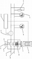
Fig. 1 shows the overall schematic construction of electrical switching system of the present utility model.But electrical switching system detection line electric current, and judgement connects the duty of consumer in the line, thus control program can be carried out control action, as the control circuit switch on and off etc.For example, if system judgement consumer enters holding state, but this electric switch open-circuit line is thoroughly eliminated the stand-by power consumption of consumer.This electric switch also can utilize the current value that detects to calculate new detection threshold.This control circuit of electrical switch can be powered by current sensing means, does not need other power-supply system, thereby has saved cost.Supply line can manually be connected/cut off to this electric switch also.
See also Fig. 1, when being connected to the consumer on socket 109,110 or connecting on the line consumer 111 when needing power supply, operating personnel's operating grip 103 makes force transferring structure 113 move, and drives movable contact spring 104 and piece of magnetic material 107 and moves.When moving to certain position, movable contact spring 104 is connected circuit 101 and 102, thereby has realized the consumer on socket 109,110 and the power supply that is connected consumer 111 grades on the line.Piece of magnetic material 107 due to magnetic force, is adsorbed on electromagnet 108 at this moment.Even if it is motionless that operating personnel's shut-down operation, force transferring structure 113 are still held by piece of magnetic material 107, thereby make supply line keep conducting.In the design, the conducting of circuit and do not keep and need consume electric energy.
When no current on circuit 101 passed through, current transformer 105 did not produce output current, thereby ON-OFF control circuit 112 does not consume any energy without working power.When being connected in the consumer on socket 109,110 and/or connecting that on the line consumer 111 is started working and during current drain, working current current flowing mutual inductor 105.The output current signal of Current Transformer Secondary side is as the input of ON-OFF control circuit 112.ON-OFF control circuit 112 is converted to working power with this input signal, guarantees inner each circuit operation.Simultaneously, ON-OFF control circuit 112 also is used for this input signal the duty of consumer on the judgement circuit and carries out corresponding control operation, as sends sound and light signal, executing data communication or gauge tap break-make etc.For example: if the judgement consumer is in holding state, ON-OFF control circuit 112 can discharge electromagnetic energy to electromagnet 108 according to program setting, the feature of this electromagnetic energy is the magnetic field mutual exclusion of its magnetic field that produces on electromagnet 108 and piece of magnetic material 107, thereby makes piece of magnetic material 107 break away from electromagnet 108.At this moment, force transferring structure 113 resets, and drives movable contact spring 104 line disconnections 101 and 102, thereby has thoroughly eliminated the stand-by power consumption that is connected in the equipment on circuit, and the equipment of also having avoided online standby to cause suffers the impact of voltage fluctuation.
ON-OFF control circuit 112 is by the current value on current transformer 105 detection lines.ON-OFF control circuit 112 can gather current current value, calculates accordingly and stores to be new current threshold, and judge the consumer duty according to this current threshold, thereby improved the applicability of system.
This system also can switch on and off supply line 101,102 as required by operating personnel's Manual operation handle 103, thereby has improved the dirigibility of system.
In the utility model, electric power system can for single-phase, also can be multiphase system.
The first embodiment of electrical switching system
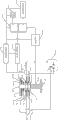
Fig. 2 shows the structure of the first embodiment of electrical switching system.Electrical switching system comprises three parts: contactor assembly, current transformer 212 and ON-OFF control circuit, wherein the contactor assembly is arranged on supply line 201, in 202, keep conducting in the under-stream period chien shih supply line that is connected to consumer in supply line's (or socket 219) always.
ON-OFF control circuit connects current transformer 212, on the one hand input signal is converted to working power so that its internal circuit operation, judge on the other hand the duty of consumer in supply line according to output signal, and according to the duty executivecontrol function, comprise and send sound and light signal, executing data communication or gauge tap break-make etc.
In the present embodiment, the contactor assembly comprises shell mechanism 204,205,220, switch spindle 203, pressure spring 208, movable contact spring 209,221, stationary contact 206,207,222,223, magnet 210 and electromagnet 211.ON-OFF control circuit comprises rectifying and voltage-stabilizing module 213, signal processing module 214, energy-storage module 218, microprocessor 215, imput output circuit 217, display module 216.
When the electrical equipment in being connected in socket 219 need be powered, the user can manually press switch spindle 203. Movable contact spring 209 and 221 are installed on switch spindle 203, and movable contact spring 209 and 221 can move down with switch spindle, and connects respectively stationary contact 206,207 and 222,223, thereby circuit is connected, at this moment, and the iron core adhesive of magnet 210 and electromagnet 211.As operating personnel no longer during the push switch main shaft, the iron core of magnet 210 and electromagnet 211 still keeps attracting state, thereby kept between movable contact spring 209 and stationary contact 206,207 and the contact between movable contact spring 221 and stationary contact 222,223, realized the conducting of supply line.
At this moment, if the consumer that is connected on socket 219 enters duty, this consumer can and produce load current I1 by the socket power taking.When current transformer 212 detects load current I1 in circuit, induce electric current I 2 at its secondary side.These electric current I 2 parts flow into rectifying and voltage-stabilizing module 213, and a part flows into signal processing module 214.Flow into the electric current of rectifying and voltage-stabilizing module 213 through after processing, produce stable output voltage, for other circuit of ON-OFF control circuit provide power supply.Input microprocessor 215 after signal processing module 214 is processed the current signal that flows into.In microprocessor 215, the program of operation gathers and computing the current signal of input, with the state of judgement electrical equipment.
Set forth as seen thus, system only has when consumer is worked, and just can induce electric current I 2 in current transformer 212, and ON-OFF control circuit also just starts; And when on socket during without electricity consumption equipment, perhaps be connected with consumer on socket and equipment when not having power consumption, and even if switch spindle 203 is pressed, because electric current I 1 is zero, so I2 is also zero, ON-OFF control circuit is not worked, and does not also expend any energy.
Energy-storage module 218 is arranged in ON-OFF control circuit.This module can obtain energy from the output of rectifying and voltage-stabilizing module 213, and stores in the mode of electromagnetic energy.Energy-storage module 218 can be controlled by the output signal of microprocessor 215, and the electromagnetic energy that stores is discharged in electromagnet 211.Electromagnet 211 can produce the acting force of inhaling mutually or repelling each other to magnet 210 due to the difference of coil winding direction and direction of current.
Input/output module 217 is arranged in ON-OFF control circuit, the input quantity of input/output module 217 can be digital quantity and analog quantity, as the input quantity of microprocessor 215, the state of input/output module 217 input quantities can be gathered by microprocessor 215, and controls corresponding program setting and execution.The output function of input/output module 217 can be switching value and analog quantity, in order to control relevant auxiliary device.Input/output module also can be the interface with data communication facility, in order to carry out exchanges data with other equipment.
Has microprocessor 215 in ON-OFF control circuit.Various programming devices and accessory circuit thereof that microprocessor can be MCU, DSP and can programme and use.After microprocessor 215 starts, the output of collection signal processing module 214, its inner program is carried out computing and judgement, thereby determines consumer duty in circuit.But microprocessor 215 is the importation of Gather and input output module 217 also, and comes execution control function according to these signal conditions.
For example, when the program of microprocessor 215 determined disconnecting circuit, microprocessor 215 sent order to energy-storage module 214, carried electromagnetic energy to electromagnet 211.When the elastic force that the repulsion that produces when electromagnet 211 adds upper spring 208 is enough to overcome the suction of magnet 210 on switch spindle, switch spindle moves up, thereby the movable contact spring on the drive switch spindle 209 and 221 moves up, and contacting of disengaging and corresponding stationary contact disconnects current supply circuit.
But microprocessor 215 is the output signal of collection signal processing module 214 also, after the process algorithm process, as new threshold value, in order to judging the state of consumer in circuit, thereby make this ON-OFF control circuit can adapt to different electrical equipments and combination thereof the numerical value that produces.
This shows, when ON-OFF control circuit is cut off current supply circuit, will thoroughly disconnect the power supply of the consumer in socket, also will cut off the power supply of self control system simultaneously.At this moment, any energy of not loss of ON-OFF control circuit, thus further saved electric energy.And consumer is thoroughly excised from power supply grid, except saves energy, also can avoid its net voltage fluctuation that causes such as be struck by lightning to impact, and guarantees device security.In addition, do not have supply voltage in socket this moment, can ensure the Electrical Safety of the colonies such as old man and children.
This switch also can manually be extracted switch spindle at any time except being controlled disconnecting circuit by microprocessor, cuts off power devices, thereby has brought greater flexibility.
The second embodiment of electrical switching system
Fig. 3 shows the structure of the second embodiment of electrical switching system of the present utility model.Electrical switching system comprises three parts: contactor assembly, current transformer 312 and ON-OFF control circuit, wherein the contactor assembly is arranged on supply line 301, in 302, keep conducting in the under-stream period chien shih supply line that is connected to consumer in supply line's (or socket 319) always.
Current transformer 312 is arranged on supply line 301, in 302, in supply line no current by the time do not produce output current, duration of work at consumer, working current in supply line is through current transformer, and the output sensor current signal of Current Transformer Secondary side is as the input signal of ON-OFF control circuit.
ON-OFF control circuit connects current transformer 312, on the one hand input signal is converted to working power so that its internal circuit operation, judge on the other hand the duty of consumer in supply line according to output signal, and according to the duty executivecontrol function, comprise and send sound and light signal, executing data communication or gauge tap break-make etc.
In the present embodiment, the contactor assembly comprises shell mechanism 304,305,320, switch spindle 303, tension spring 308, movable contact spring 309,321, stationary contact 306,307,322,323, magnet 310 and electromagnet 311.ON-OFF control circuit comprises rectifying and voltage-stabilizing module 313, signal processing module 314, energy-storage module 318, microprocessor 315, imput output circuit 317, display module 316.
The key distinction of the present embodiment and the first embodiment is position and the effect of spring.In the first embodiment, pressure spring is between switch spindle and electromagnet.When operating personnel pressed switch spindle, pressure spring produced compression set, and produced the power that switch spindle is rebounded.
And in a second embodiment, rebound 308 for tension spring, and the one end acts on the shell 304,305 of equipment, and the other end acts on switch spindle 303.When operating personnel pressed switch spindle 303, tension spring 308 produced tensile deformation, thereby produced the power that switch spindle 303 is retracted original position.
The 3rd embodiment of electrical switching system
Fig. 3 shows the structure of the 3rd embodiment of electrical switching system of the present utility model.Electrical switching system comprises three parts: contactor assembly, current transformer 412 and ON-OFF control circuit, wherein the contactor assembly is arranged on supply line 401, in 402, keep conducting in the under-stream period chien shih supply line that is connected to consumer in supply line's (or socket 419) always.
ON-OFF control circuit connects current transformer 412, on the one hand input signal is converted to working power so that its internal circuit operation, judge on the other hand the duty of consumer in supply line according to output signal, and according to the duty executivecontrol function, comprise and send sound and light signal, executing data communication or gauge tap break-make etc.
In the present embodiment, the contactor assembly comprises shell 404,405,420, switch spindle 403, movable contact spring 409,421, stationary contact 406,407,422,423, magnet 410, electromagnet 411, the first permanent magnet 426,428, the second permanent magnet 425,427.ON-OFF control circuit comprises rectifying and voltage-stabilizing module 413, signal processing module 414, energy-storage module 418, microprocessor 415, imput output circuit 417, display module 416.
Compare with the first embodiment, the 3rd embodiment has increased by 425,426 and 427,428 permanent magnet, removed the spring in the first embodiment and the second embodiment, it is characterized in that between the second permanent magnet 425, the first permanent magnets 426 and the second permanent magnet 427, the first permanent magnets 428 between magneticaction attract mutually.
In the present embodiment, when switch is in off-position, the second permanent magnet 425 and the first permanent magnet 426 and the second permanent magnet 427 and the first permanent magnet 428 adhesives, magnetic force between them is greater than the suction between magnet 410 and electromagnet 411, thereby make switch spindle 403 be in a settling position, at this moment, the movable contact spring 409 and 421 stationary contacts of getting along well their correspondences that are installed on switch spindle 403 contact.When operating personnel press switch spindle 403, the suction that switch spindle 403 applied pressures are produced greater than the second permanent magnet 425 and the first permanent magnet 426 and the second permanent magnet 427 and the first permanent magnet 428 adhesives, thereby make switch spindle 403 move down, drive movable contact spring 409 and 421 and be pressed on its corresponding stationary contact, make line conduction.When switch spindle 403 moved to certain position, the suction between magnet 410 and electromagnet 411 iron cores had overcome the power that suction between the second permanent magnet 425 and the first permanent magnet 426 and the second permanent magnet 427 and the first permanent magnet 428 and static contact 409 and 421 elastic deformations produce.Even if this moment, operating personnel cancelled push switch main shaft 403, magnet 410 also can be adsorbed on switch spindle 403 on electromagnet 411 iron cores, and switch spindle 410 drives movable contact spring and keeps line conduction.
When on-off control system detected system and need to cut off the electricity supply, energy-storage module 418 received the instruction of microprocessor 415, to the coil discharge of electromagnet 411.Mutual exclusion occurs in the magnetic field that this electric current produces and the magnetic field of magnet 410, and magnet 410 and switch spindle 403 are pushed away electromagnet, moves up.When move to certain apart from the time, adhesive between the second permanent magnet 425 and the first permanent magnet 426 and the second permanent magnet 427 and the first permanent magnet 428, switch spindle 403 drove movable contact springs 409 and 421 and broke away from its corresponding stationary contacts this moment, thereby cut off circuit.
The difference of above-mentioned three embodiment is: the stored energy mechanism of assisting switch to reset.In the first embodiment, be pressure spring.When operating personnel's depress switch main shaft was connected circuit, pressure spring produced compression set and energy storage.This energy discharges when thereby electromagnet is pushed the magnet line disconnection of switch spindle bottom open, makes the cut-out of circuit more fast reliable.In a second embodiment, be tension spring.When operating personnel's depress switch main shaft was connected circuit, tension spring produced tensile deformation and energy storage.And in the 3rd embodiment, stored energy mechanism is illustrated the first permanent magnet 426,428, the second permanent magnet 425,427.When operating personnel's depress switch main shaft was connected circuit, the relative distance between the second permanent magnet 425 and the first permanent magnet 426 and the second permanent magnet 427 and the first permanent magnet 428 changed, and has realized energy storage.
Above-described embodiment is to provide to those of ordinary skills and realizes and use of the present utility model; those of ordinary skills can be in the situation that do not break away from invention thought of the present utility model; above-described embodiment is made various modifications or variation; thereby protection domain of the present utility model do not limit by above-described embodiment, and should be the maximum magnitude that meets the inventive features that claims mention.
Claims (7)
1. an electrical switching system, is characterized in that, comprises contactor assembly, current transformer and ON-OFF control circuit, wherein:
The contactor assembly is arranged in supply line, keeps conducting in the under-stream period chien shih supply line that is connected to consumer in supply line always;
Current transformer is arranged in supply line, in supply line no current by the time do not produce output current, duration of work at consumer, working current in supply line is through current transformer, and the output sensor current signal of Current Transformer Secondary side is as the input signal of ON-OFF control circuit;
ON-OFF control circuit connects current transformer, input signal is converted to working power so that the internal circuit operation.
2. electrical switching system according to claim 1, is characterized in that, ON-OFF control circuit further comprises rectifying and voltage-stabilizing module, signal processing module, energy-storage module, microprocessor, imput output circuit, wherein:
Rectifying and voltage-stabilizing module connection current transformer and signal processing module, energy-storage module, microprocessor, imput output circuit, the induction current of received current mutual inductor secondary side output, be processed into stable output voltage, for other modules of ON-OFF control circuit provide power supply;
Signal processing module connects current transformer, and the induction current of received current mutual inductor secondary side output inputs to microprocessor after processing;
Energy-storage module connects microprocessor, obtains energy and stores in the mode of electromagnetic energy from the output of rectifying and voltage-stabilizing module, is subjected to the output signal of microprocessor to control the electromagnetic energy that discharges storage;
Input/output module connects microprocessor, and with the input quantity as microprocessor, the output quantity of input/output module is in order to control auxiliary device by the microprocessor collection for its input quantity.
3. electrical switching system according to claim 2, is characterized in that, input/output module has data communication interface in order to carry out exchanges data with other equipment.
4. electrical switching system according to claim 2, is characterized in that, the contactor assembly further comprises shell, switch spindle, pressure spring, movable contact spring, magnet and electromagnet, wherein:
Movable contact spring is installed on switch spindle, and when consumer need be powered, switch spindle was pressed, and the movable contact spring that is arranged on switch spindle moves with switch spindle, connect in supply line stationary contact so that supply line connect;
Magnet is arranged on switch spindle, electromagnet is arranged near the relative position magnet, pressure spring is arranged between electromagnet and magnet, the iron core adhesive of magnet and electromagnet and keep attracting state when supply line connects, pressure spring produces compression set, produces switch spindle is popped into position the power of putting;
Energy-storage module discharges the electromagnetic energy of storage to electromagnet, and electromagnet produces due to the difference of coil winding direction and direction of current the acting force that repels each other to magnet.
5. electrical switching system according to claim 2, is characterized in that, the contactor assembly further comprises shell, switch spindle, tension spring, movable contact spring, magnet and electromagnet, wherein:
Movable contact spring is installed on switch spindle, and when consumer need be powered, switch spindle was pressed, and the movable contact spring that is arranged on switch spindle moves with switch spindle, connect in supply line stationary contact so that supply line connect;
Magnet is arranged on switch spindle, electromagnet is arranged near the relative position magnet, tension spring one end acts on shell, the other end acts on switch spindle, the iron core adhesive of magnet and electromagnet and keep attracting state when supply line connects, tension spring produces tensile deformation, produces the power that switch spindle is retracted original position;
Energy-storage module discharges the electromagnetic energy of storage to electromagnet, and electromagnet produces due to the difference of coil winding direction and direction of current the acting force that repels each other to magnet.
6. electrical switching system according to claim 2, is characterized in that, the contactor assembly further comprises shell, switch spindle, movable contact spring, magnet, electromagnet, the first permanent magnet, the second permanent magnet, wherein:
The first permanent magnet is arranged on shell, the second permanent magnet is arranged on switch spindle, when electric switch is in off-position, the first permanent magnet and the second permanent magnet adhesive, make switch spindle be in a settling position, so that stationary contact contact in the supply line of the discord of the movable contact spring on switch spindle correspondence;
When consumer need be powered, switch spindle was pressed, and the movable contact spring that is arranged on switch spindle moves with switch spindle, connect in supply line stationary contact so that supply line connect;
Magnet is arranged on switch spindle, and electromagnet is arranged near the relative position magnet, and when connecting in supply line, magnet is adsorbed on switch spindle on electromagnet core and keeps attracting state;
Energy-storage module discharges the electromagnetic energy of storage to electromagnet, electromagnet is due to the difference of coil winding direction and direction of current, magnet is produced the acting force that repels each other, when moving to certain distance, adhesive between the first permanent magnet and the second permanent magnet, switch spindle drives movable contact spring and breaks away from its corresponding stationary contact, thereby cuts off circuit.
7. the described electrical switching system of any one according to claim 4-6, is characterized in that, a manual operating grip is installed on switch spindle, during operating grip, can manually disconnect/connect supply line.
Priority Applications (1)
| Application Number | Priority Date | Filing Date | Title |
|---|---|---|---|
| CN 201220456556 CN203025493U (en) | 2012-09-07 | 2012-09-07 | Electrical switching system |
Applications Claiming Priority (1)
| Application Number | Priority Date | Filing Date | Title |
|---|---|---|---|
| CN 201220456556 CN203025493U (en) | 2012-09-07 | 2012-09-07 | Electrical switching system |
Publications (1)
| Publication Number | Publication Date |
|---|---|
| CN203025493U true CN203025493U (en) | 2013-06-26 |
Family
ID=48649463
Family Applications (1)
| Application Number | Title | Priority Date | Filing Date |
|---|---|---|---|
| CN 201220456556 Expired - Fee Related CN203025493U (en) | 2012-09-07 | 2012-09-07 | Electrical switching system |
Country Status (1)
| Country | Link |
|---|---|
| CN (1) | CN203025493U (en) |
Cited By (3)
| Publication number | Priority date | Publication date | Assignee | Title |
|---|---|---|---|---|
| CN104090189A (en) * | 2014-07-21 | 2014-10-08 | Tcl集团股份有限公司 | Device working state detecting method and device |
| CN108669930A (en) * | 2018-07-28 | 2018-10-19 | 马鞍山悠生活网络文化科技有限公司 | A kind of use for electronic products rotary exhibition table and its operating method |
| CN110931323A (en) * | 2019-12-12 | 2020-03-27 | 张静 | Energy-saving circuit breaker |
-
2012
- 2012-09-07 CN CN 201220456556 patent/CN203025493U/en not_active Expired - Fee Related
Cited By (5)
| Publication number | Priority date | Publication date | Assignee | Title |
|---|---|---|---|---|
| CN104090189A (en) * | 2014-07-21 | 2014-10-08 | Tcl集团股份有限公司 | Device working state detecting method and device |
| CN104090189B (en) * | 2014-07-21 | 2017-12-15 | Tcl集团股份有限公司 | A kind of equipment working state detection method and equipment working state detection means |
| CN108669930A (en) * | 2018-07-28 | 2018-10-19 | 马鞍山悠生活网络文化科技有限公司 | A kind of use for electronic products rotary exhibition table and its operating method |
| CN110931323A (en) * | 2019-12-12 | 2020-03-27 | 张静 | Energy-saving circuit breaker |
| CN110931323B (en) * | 2019-12-12 | 2020-10-30 | 乐清市泰博恒电子科技有限公司 | Energy-saving circuit breaker |
Similar Documents
| Publication | Publication Date | Title |
|---|---|---|
| CN102780205B (en) | Electric leakage detecting protection circuit | |
| CN102457042B (en) | Novel electricity leakage detection protection circuit | |
| CN203025493U (en) | Electrical switching system | |
| CN103676679A (en) | Electrical switch system | |
| CN201477455U (en) | Temperature control system with detection and control of contactor faults | |
| CN201515205U (en) | Earth leakage checking protective circuit | |
| CN201774225U (en) | Electric leakage detecting protection circuit | |
| CN203553882U (en) | Transformer low-voltage tripping automatic reclosing device | |
| CN101860005B (en) | Uninterrupted power test residual current protective device | |
| CN206712446U (en) | A kind of electromagnetic leakage protection circuit | |
| CN105261530A (en) | Multi-stroke realizing circuit and multi-stroke control method for circuit breakers | |
| CN201655679U (en) | Low-voltage contactor delay circuit device | |
| CN101162386A (en) | Electric appliance without power consumption servo device | |
| CN107978495A (en) | A kind of protective device of breaker | |
| CN203673280U (en) | Relay-controlled low-power control system | |
| CN208078643U (en) | A kind of device with master-slave back-up lightning protection device | |
| CN201774224U (en) | Novel electric-leakage detection protection circuit | |
| CN203180491U (en) | Electric leakage protection device | |
| CN207504635U (en) | A kind of double power-supply automatic transferring device | |
| CN201623379U (en) | Operation controller of switch cabinet | |
| TW201707323A (en) | Fully electronic exchange overcurrent breaker | |
| CN102340125B (en) | Novel leakage detection protection circuit | |
| CN104362578B (en) | Can reclosing RCCB | |
| CN102377164B (en) | Energy-efficient leakage detection protection circuit | |
| CN101944716A (en) | Electricity leakage detection protective circuit |
Legal Events
| Date | Code | Title | Description |
|---|---|---|---|
| C14 | Grant of patent or utility model | ||
| GR01 | Patent grant | ||
| CF01 | Termination of patent right due to non-payment of annual fee |
Granted publication date: 20130626 Termination date: 20180907 |
|
| CF01 | Termination of patent right due to non-payment of annual fee |