CN203008959U - Evacuation platform - Google Patents
Evacuation platform Download PDFInfo
- Publication number
- CN203008959U CN203008959U CN 201220586095 CN201220586095U CN203008959U CN 203008959 U CN203008959 U CN 203008959U CN 201220586095 CN201220586095 CN 201220586095 CN 201220586095 U CN201220586095 U CN 201220586095U CN 203008959 U CN203008959 U CN 203008959U
- Authority
- CN
- China
- Prior art keywords
- pin
- brace summer
- connector
- assembly
- evacuation platform
- Prior art date
- Legal status (The legal status is an assumption and is not a legal conclusion. Google has not performed a legal analysis and makes no representation as to the accuracy of the status listed.)
- Expired - Fee Related
Links
Images


Abstract
The utility model discloses an evacuation platform which comprises a support beam, a platform panel, a pin shaft component and a fixing structure, wherein the platform panel is composed of multiple support plates which are arranged in parallel. The multiple support plates are arranged on the support beam. The pin roll component perpendicularly penetrates through side walls of the multiple support plates and is connected with the multiple support plates in parallel. The fixing structure is fixedly connected with the pin shaft component and the support beam. The pin shaft component is composed of at least one pin shaft, and at least one pin shaft is a steel pin shaft. Due to the fact that the steel pin shaft is used as a main stressed member, the evacuation platform can enhance mechanical strength and anti-fatigue performance of the pin shaft component.
Description
Technical field
The utility model relates to a kind of evacuation platform.
Background technology
Application number is that 201120041442.2 patent discloses a kind of evacuation platform in subway, the connection bearing pin that described evacuation platform in subway comprises crossbeam, is positioned at a plurality of gripper shoes placed side by side on described crossbeam and vertically runs through described gripper shoe sidewall, described connection bearing pin is with a plurality of gripper shoes placed side by side and be unified into a platform, and described two adjacent platforms are by described crossbeam tandem array; It is characterized in that, this comprises for the locking device that described platform is fixed on described crossbeam, is provided with at least one locking device on described each crossbeam.The disclosed evacuation platform in subway of the utility model is together in parallel gripper shoe placed side by side successively by the connection bearing pin is set, and forms an integral body, and by locking device, gripper shoe is fixed on crossbeam, guarantees the fixing of gripper shoe and crossbeam; Adjacent gripper shoe sidewall fits simultaneously, make gripper shoe arrange the platform that forms and do not have the gap, guarantee the safety that personnel walk, avoided harm that the person is caused, subway tunnel train was held to form and was reached the tunnel wind of 300KG/ square metre, was born by bearing pin and these power are concentrated, and the fatigue resistance of the connection bearing pin in technique scheme has directly affected safety and the application life of platform, therefore need a kind of mechanical strength badly large, and the strong evacuation platform of anti-fatigue ability.
The utility model content
Fixing not firm and have the problem of personal safety hidden danger for solving existing subway evacuation platform, the utility model discloses a kind of evacuation platform, to reach the purpose of effectively gripper shoe and brace summer being fixed, can be used for a long time and reduce harm.
The technical solution of the utility model is as follows: a kind of evacuation platform, comprise brace summer, platform panel, Assembly of pin and fixed structure, and described platform panel comprises a plurality of gripper shoes that are arranged side by side; Described a plurality of gripper shoe is arranged on described brace summer; Described Assembly of pin vertically runs through described a plurality of gripper shoe sidewall and described a plurality of gripper shoes is connected in parallel; Described fixed structure is fixedly connected with described Assembly of pin, and described Assembly of pin comprises at least one bearing pin, and in described bearing pin, at least one is the steel pin axle.
Preferably, described Assembly of pin comprises steel pin axle and the glass fiber reinforced plastic bearing pin that is set up in parallel, and the external diameter of described steel pin axle is greater than the external diameter of described glass fiber reinforced plastic bearing pin.
Preferably, described gripper shoe is section bar, and the cross section of described section bar is the structure of closed upper part; The sidewall of described adjacent profiles fits.
Preferably, described glass fiber reinforced plastic bearing pin is provided with the draw-in groove that the sidewall with described section bar is complementary, and described glass fiber reinforced plastic bearing pin is by the sidewall of the described section bar of described draw-in groove clamping.
Preferably, described adjacent platforms panel is by described brace summer tandem array.
Preferably, described fixed structure comprises the first connector that is fixedly connected with described Assembly of pin and the second connector that is fixedly connected with described brace summer; Described the first connector is fixedly connected with described the second connector.
Preferably, described brace summer and vertical setting of described a plurality of gripper shoes, described the first connector is the hook that is mounted on described Assembly of pin; Described the second connector is the fixed head that is connected on described brace summer; The free end of described hook is connected with described fixed head screw.
Preferably, described fixed head be arranged at described brace summer the bottom buckle or be welded in the angle bar of the one or both sides of described brace summer.
Preferably, described brace summer and vertical setting of described a plurality of gripper shoes, described the first connector is the hook that is mounted on described Assembly of pin, described the second connector is to be socketed on U-shaped of described brace summer bottom; The free end of described U-shaped is connected with sleeve; The free end of described hook is connected with described telescopic screw.
Preferably, described brace summer and vertical setting of described a plurality of gripper shoes, described the first connector is the link that is mounted on described Assembly of pin; Described the second connector is the frame type spare that is socketed on described brace summer; The free end of described link is connected with described frame type spare.
Adopt the beneficial effect of above technical scheme: one, evacuation platform comprises brace summer, platform panel, Assembly of pin and fixed structure, and the platform panel comprises a plurality of gripper shoes that are arranged side by side; A plurality of gripper shoes are arranged on brace summer; Assembly of pin vertically runs through a plurality of gripper shoe sidewalls and a plurality of gripper shoes is connected in parallel; Fixed structure is fixedly connected with Assembly of pin, and Assembly of pin comprises at least one bearing pin, and in bearing pin, at least one is the steel pin axle, as the main stress parts, can strengthen mechanical strength and the anti-fatigue performance of Assembly of pin due to the steel pin axle; Two, Assembly of pin comprises steel pin axle and the glass fiber reinforced plastic bearing pin that is set up in parallel, and can Assembly of pin is fixedly connected with gripper shoe by the glass fiber reinforced plastic bearing pin.
Description of drawings
In order to be illustrated more clearly in the utility model embodiment or technical scheme of the prior art, the below will do to introduce simply to the accompanying drawing of required use in embodiment or description of the Prior Art, apparently, accompanying drawing in the following describes is only embodiment more of the present utility model, for those of ordinary skills, under the prerequisite of not paying creative work, can also obtain according to these accompanying drawings other accompanying drawing.
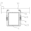
Fig. 1 is the structural representation of evacuation platform in the disclosed evacuation platform embodiment 1 of the utility model;
Fig. 2 is the structural representation of fixed structure in the disclosed evacuation platform embodiment 1 of the utility model;
Fig. 3 is the structural representation of Assembly of pin in the disclosed evacuation platform embodiment 2 of the utility model;
Fig. 4 is the structural representation of evacuation platform in the disclosed evacuation platform embodiment 3 of the utility model;
Fig. 5 is the structural representation of Assembly of pin in the disclosed evacuation platform embodiment 4 of the utility model;
Fig. 6 is the structural representation of evacuation platform in the disclosed evacuation platform embodiment 5 of the utility model;
Fig. 7 is the structural representation of fixed structure in the disclosed evacuation platform embodiment 6 of the utility model;
Fig. 8 is the structural representation of fixed structure in the disclosed evacuation platform embodiment 7 of the utility model;
Fig. 9 is the structural representation of fixed structure in the disclosed evacuation platform embodiment 8 of the utility model.
The title of the numeral in figure or the corresponding component of alphabetical representative:
1. brace summer 2. platform panel 21. gripper shoes 3. connect bearing pin 31. steel pin axle 32. glass fiber reinforced plastic bearing pin 411. hook 412. link 421. buckle 422. angle bar 423.U type spare 424. frame type spare 5. nut 6. sleeve 7. locking members.
The specific embodiment
Below in conjunction with the accompanying drawing in the utility model embodiment, the technical scheme in the utility model embodiment is clearly and completely described, obviously, described embodiment is only the utility model part embodiment, rather than whole embodiment.Based on the embodiment in the utility model, those of ordinary skills are not making the every other embodiment that obtains under the creative work prerequisite, all belong to the scope of the utility model protection.
Referring to Fig. 1 and Fig. 2, as shown in legend wherein, a kind of evacuation platform comprises a brace summer 1, a platform panel 2, an Assembly of pin 3 and a fixed structure, and platform panel 2 comprises a plurality of gripper shoes 21 that are arranged side by side; A plurality of gripper shoes 21 are arranged on brace summer 1; Assembly of pin 3 vertically runs through a plurality of gripper shoe 21 sidewalls and a plurality of gripper shoes 21 is connected in parallel; Fixed structure is fixedly connected with Assembly of pin 3, and Assembly of pin 3 comprises at least one bearing pin, and in bearing pin, at least one is the steel pin axle.
Fixed structure comprises one first connector that is fixedly connected with Assembly of pin 3 and is fixedly connected with the second connector with brace summer 1; The first connector is fixedly connected with described the second connector.
Brace summer 1 and the vertical setting of a plurality of gripper shoes 21, the first connector are two hooks 411 that are mounted on the Assembly of pin 3 of brace summer 1 both sides; The second connector is the buckle 421 that is connected in brace summer 1 bottom; The free end of hook 411 is connected by nut 5 with buckle 421.
At first vertically offer through hole along a plurality of gripper shoe 21 sidewalls, Assembly of pin 3 is arranged in through hole, the steel pin axle is main stressed member, can greatly improve the power ability to bear of Assembly of pin 3.
Referring to Fig. 1, Fig. 2 and Fig. 3, as shown in legend wherein, all the other are identical with described embodiment 1, and difference is, Assembly of pin 3 comprises a steel pin axle 31 and a glass fiber reinforced plastic bearing pin 32 that is set up in parallel, and the external diameter of steel pin axle 31 is greater than the external diameter of glass fiber reinforced plastic bearing pin 32.
Referring to Fig. 4, as shown in legend wherein, all the other are identical with described embodiment 2, and difference is, gripper shoe 21 is section bar, and the cross section of section bar is the structure of closed upper part; The sidewall of adjacent profiles fits.
Section bar makes Assembly of pin 3 more fixing more interspersed, and section bar has good intensity and toughness.
Embodiment 4
Referring to Fig. 5, as shown in legend wherein, all the other are identical with described embodiment 3, and difference is, glass fiber reinforced plastic bearing pin 32 is provided with the draw-in groove 321 that the sidewall with section bar is complementary, and glass fiber reinforced plastic bearing pin 32 is by the sidewall of the draw-in groove 321 described section bars of clamping.
At first glass fiber reinforced plastic bearing pin 32 is worn and injected in through hole, the draw-in groove 321 places cards of glass fiber reinforced plastic bearing pin 32 are set on the sidewall of section bar, then intert steel pin axle 31, steel pin axle 31 firmly can be fixed on gripper shoe 21.
Referring to Fig. 6, as shown in legend wherein, all the other are identical with described embodiment 4, and difference is, the adjacent platforms panel is by brace summer 1 tandem array.
Embodiment 6
Referring to Fig. 6 and Fig. 7, as shown in legend wherein, all the other are identical with described embodiment 5, and difference is, the second connector is the angle bar 422 of establishing the buckle one or both sides of the bottom that is welded in brace summer 1, and hook 411 is connected with angle bar and is connected by nut 5.
Referring to Fig. 6 and Fig. 8, as shown in legend wherein, all the other are identical with described embodiment 5, and difference is, the first connector is that to be mounted on the hook of one on Assembly of pin 3 411, the second connectors be to be socketed on U-shaped 423 of brace summer 1 bottom; The free end of U-shaped 423 is connected with sleeve 6; The free end of hook 411 is connected with sleeve 6 screws.
Embodiment 8
Referring to Fig. 6 and Fig. 9, as shown in legend wherein, all the other are identical with described embodiment 5, and difference is, brace summer 1 is the link 412 that is mounted on Assembly of pin 3 with the vertical setting of a plurality of gripper shoes 21, the first connector; The second connector is the frame type spare 424 that is socketed on brace summer 1; The free end of link 412 is connected with frame type spare 424; Frame type spare 424 connects by locking member 7 lockings.
Adopt the beneficial effect of above technical scheme: one, evacuation platform comprises brace summer, platform panel, Assembly of pin and fixed structure, and the platform panel comprises a plurality of gripper shoes that are arranged side by side; A plurality of gripper shoes are arranged on brace summer; Assembly of pin vertically runs through a plurality of gripper shoe sidewalls and a plurality of gripper shoes is connected in parallel; Fixed structure is fixedly connected with Assembly of pin, and Assembly of pin comprises at least one bearing pin, and in bearing pin, at least one is the steel pin axle, as the main stress parts, can strengthen mechanical strength and the anti-fatigue performance of Assembly of pin due to the steel pin axle; Two, Assembly of pin comprises steel pin axle and the glass fiber reinforced plastic bearing pin that is set up in parallel, and can Assembly of pin is fixedly connected with gripper shoe by the glass fiber reinforced plastic bearing pin.
Be more than the description to the utility model embodiment, by the above-mentioned explanation to the disclosed embodiments, make this area professional and technical personnel can realize or use the utility model.Multiple modification to these embodiment will be apparent concerning those skilled in the art, and General Principle as defined herein can be in the situation that do not break away from spirit or scope of the present utility model, realization in other embodiments.Therefore, the utility model will can not be restricted to these embodiment shown in this article, but will meet the widest scope consistent with principle disclosed herein and features of novelty.
Claims (10)
1. an evacuation platform, comprise brace summer, platform panel, Assembly of pin and fixed structure, and described platform panel comprises a plurality of gripper shoes that are arranged side by side; Described a plurality of gripper shoe is arranged on described brace summer; Described Assembly of pin vertically runs through described a plurality of gripper shoe sidewall and described a plurality of gripper shoes is connected in parallel; Described fixed structure is fixedly connected with described Assembly of pin and brace summer, it is characterized in that, described Assembly of pin comprises at least one bearing pin, and in described bearing pin, at least one is the steel pin axle.
2. evacuation platform according to claim 1, is characterized in that, described Assembly of pin comprises steel pin axle and the glass fiber reinforced plastic bearing pin that is set up in parallel, and the external diameter of described steel pin axle is greater than the external diameter of described glass fiber reinforced plastic bearing pin.
3. evacuation platform according to claim 2, is characterized in that, described gripper shoe is section bar, and the cross section of described section bar is the structure of closed upper part; The sidewall of described adjacent profiles fits.
4. evacuation platform according to claim 3, is characterized in that, described glass fiber reinforced plastic bearing pin is provided with the draw-in groove that the sidewall with described section bar is complementary, and described glass fiber reinforced plastic bearing pin is by the sidewall of the described section bar of described draw-in groove clamping.
5. according to claim 1-4 arbitrary described evacuation platforms, is characterized in that, described adjacent platforms panel is by described brace summer tandem array.
6. evacuation platform according to claim 5, is characterized in that, described fixed structure comprises the first connector that is fixedly connected with described Assembly of pin and the second connector that is fixedly connected with described brace summer; Described the first connector is fixedly connected with described the second connector.
7. evacuation platform according to claim 6, is characterized in that, described brace summer and vertical setting of described a plurality of gripper shoes, and described the first connector is the hook that is mounted on described Assembly of pin; Described the second connector is the fixed head that is connected on described brace summer; The free end of described hook is connected with described fixed head screw.
8. evacuation platform according to claim 7, is characterized in that, described fixed head be arranged at described brace summer the bottom buckle or be welded in the angle bar of the one or both sides of described brace summer.
9. evacuation platform according to claim 6, it is characterized in that, described brace summer and vertical setting of described a plurality of gripper shoes, described the first connector is the hook that is mounted on described Assembly of pin, described the second connector is to be socketed on U-shaped of described brace summer bottom; The free end of described U-shaped is connected with sleeve; The free end of described hook is connected with described telescopic screw.
10. evacuation platform according to claim 6, is characterized in that, described brace summer and vertical setting of described a plurality of gripper shoes, and described the first connector is the link that is mounted on described Assembly of pin; Described the second connector is the frame type spare that is socketed on described brace summer; The free end of described link is connected with described frame type spare.
Priority Applications (1)
| Application Number | Priority Date | Filing Date | Title |
|---|---|---|---|
| CN 201220586095 CN203008959U (en) | 2012-11-09 | 2012-11-09 | Evacuation platform |
Applications Claiming Priority (1)
| Application Number | Priority Date | Filing Date | Title |
|---|---|---|---|
| CN 201220586095 CN203008959U (en) | 2012-11-09 | 2012-11-09 | Evacuation platform |
Publications (1)
| Publication Number | Publication Date |
|---|---|
| CN203008959U true CN203008959U (en) | 2013-06-19 |
Family
ID=48600565
Family Applications (1)
| Application Number | Title | Priority Date | Filing Date |
|---|---|---|---|
| CN 201220586095 Expired - Fee Related CN203008959U (en) | 2012-11-09 | 2012-11-09 | Evacuation platform |
Country Status (1)
| Country | Link |
|---|---|
| CN (1) | CN203008959U (en) |
Cited By (3)
| Publication number | Priority date | Publication date | Assignee | Title |
|---|---|---|---|---|
| CN103321674A (en) * | 2013-07-11 | 2013-09-25 | 南通美固复合材料有限公司 | Composite evacuation platform |
| CN103806936A (en) * | 2012-11-09 | 2014-05-21 | 江苏源盛复合材料技术股份有限公司 | Evacuation platform |
| CN110665133A (en) * | 2019-09-23 | 2020-01-10 | 川消消防工程有限公司 | Fire-fighting evacuation platform for sudden fire |
-
2012
- 2012-11-09 CN CN 201220586095 patent/CN203008959U/en not_active Expired - Fee Related
Cited By (4)
| Publication number | Priority date | Publication date | Assignee | Title |
|---|---|---|---|---|
| CN103806936A (en) * | 2012-11-09 | 2014-05-21 | 江苏源盛复合材料技术股份有限公司 | Evacuation platform |
| CN103321674A (en) * | 2013-07-11 | 2013-09-25 | 南通美固复合材料有限公司 | Composite evacuation platform |
| CN110665133A (en) * | 2019-09-23 | 2020-01-10 | 川消消防工程有限公司 | Fire-fighting evacuation platform for sudden fire |
| CN110665133B (en) * | 2019-09-23 | 2020-09-18 | 川消消防工程有限公司 | Fire-fighting evacuation platform for sudden fire |
Similar Documents
| Publication | Publication Date | Title |
|---|---|---|
| CN204126358U (en) | The high electric pole of a kind of safety carries establishes device | |
| CN203008959U (en) | Evacuation platform | |
| CN204185061U (en) | Home lift beaming device | |
| CN205778885U (en) | A kind of shield machine reaction frame | |
| CN103806936A (en) | Evacuation platform | |
| CN203187299U (en) | C-shaped steel lifting appliance | |
| CN203569871U (en) | Installation structure for scaffold | |
| CN203079487U (en) | Large-tonnage elevator car bottom | |
| CN201140784Y (en) | Railing chuck | |
| CN205089059U (en) | Electric power rail convenient to overhaul | |
| CN204055778U (en) | High speed train traction transformer mounting rail structure | |
| CN206385822U (en) | A kind of civil engineering guard rail | |
| CN201857557U (en) | Single hoisting track | |
| CN205224568U (en) | Safety protection lift platform | |
| CN201539099U (en) | Adjusting seam plate template | |
| CN205134556U (en) | Improved connecting piece for steel -structure beam columns | |
| CN218028676U (en) | Anti-fracture floor splicing device | |
| CN202727093U (en) | Tensioning device of prefabricated box girder | |
| CN206517337U (en) | A kind of suspension cable mounting structure of photovoltaic plant | |
| CN202560246U (en) | Roadway junction bracket for mining | |
| CN202744940U (en) | Reinforced double-channel bridge | |
| CN201184134Y (en) | Inverse well drill reverse T type dismountable drill rig | |
| CN203080752U (en) | Locking piece connecting structure of corner of curtain wall unit | |
| CN215475430U (en) | Novel semitrailer rib pressing breast board | |
| CN202440830U (en) | Lattice tower footing |
Legal Events
| Date | Code | Title | Description |
|---|---|---|---|
| C14 | Grant of patent or utility model | ||
| GR01 | Patent grant | ||
| TR01 | Transfer of patent right |
Effective date of registration: 20200123 Address after: 313000 Zhejiang city of Huzhou province with the old building in the town of Nanxun Road No. 2 -8 Patentee after: ZHEJIANG DEYILONG TECHNOLOGY CO.,LTD. Address before: Suzhou City, Jiangsu province 215000 Fengting Avenue Suzhou Industrial Park No. 733 Patentee before: JIANGSU TOP COMPOSITE TECHNOLOGY Co.,Ltd. |
|
| TR01 | Transfer of patent right | ||
| CF01 | Termination of patent right due to non-payment of annual fee |
Granted publication date: 20130619 Termination date: 20211109 |
|
| CF01 | Termination of patent right due to non-payment of annual fee |