CN202985424U - Auxiliary locking structure for installing turbine - Google Patents
Auxiliary locking structure for installing turbine Download PDFInfo
- Publication number
- CN202985424U CN202985424U CN 201220615627 CN201220615627U CN202985424U CN 202985424 U CN202985424 U CN 202985424U CN 201220615627 CN201220615627 CN 201220615627 CN 201220615627 U CN201220615627 U CN 201220615627U CN 202985424 U CN202985424 U CN 202985424U
- Authority
- CN
- China
- Prior art keywords
- turbine
- locked
- locking structure
- installing
- auxiliary locking
- Prior art date
- Legal status (The legal status is an assumption and is not a legal conclusion. Google has not performed a legal analysis and makes no representation as to the accuracy of the status listed.)
- Expired - Fee Related
Links
Images


Abstract
The utility model provides an auxiliary locking structure for installing a turbine. No matter how long the shaft of a to-be-locked turbine is, the to-be-locked turbine can also be applicable to the auxiliary locking structure for installing the turbine, so that the auxiliary locking structure for installing the turbine has good generality. The auxiliary locking structure for installing the turbine comprises a clamping head plate, and bayonets which are matched with the shape and sizes of a turbine head are arranged on the clamping head plate. The auxiliary locking structure for installing the turbine further comprises a supporting plate. The auxiliary locking structure for installing the turbine is characterized in that an air cylinder seat of an air cylinder is tightly fixed on the upper surface of the base, an air cylinder arm of the air cylinder is tightly arranged on the bottom surface of the supporting plate, and the air cylinder moves at a vertical direction. A turbine head of a to-be-locked turbine is arranged in the corresponding bayonets in a clamping mode, the middle portion shaft end of the to-be-locked turbine is supported at the supporting plate, and the to-be-locked end of the to-be-locked turbine is exposed outside the opening structure. A sliding block is arranged on the bottom portion of the clamping head plate, the sliding block is embedded in a straight line rail of the base, and the straight line rail is perpendicular to the upright surface of the clamping head plate.
Description
Technical field
The utility model relates to the booster turbine components fixing device, is specially a kind of turbine the auxiliary lock locking structure is installed.
Background technology
In the installation process of booster turbine, for locking nut, must fix turbine head, shape due to turbine head during installation is different, adopt a kind of custom-designed chuck plate on the ground horizontal fix, the bayonet socket of the multiple turbine head shape and size such as circle, triangle, hexagon is arranged on chuck plate, like this for different turbine heads, do not need the replacing instrument.But practical operation is sometimes not too convenient, this just need to adopt horizontal installation with the turbine exemplar, for this reason, we have designed base, support, support, chuck plate are installed on base side by side, be provided with the brace table corresponding with bayonet socket on support, to solve horizontally-mounted problem, yet, the problem that this structure exists is, the turbine exemplar needs an end of locking nut to ride over brace table on support, because the distance between existing support, chuck plate is fixed, inapplicable in short-term when the axle of worm gear to be locked, cause its versatility poor.
The utility model content
For above-mentioned situation, the utility model provides a kind of turbine that the auxiliary lock locking structure is installed, no matter the axial length of its worm gear to be locked is short, all can be suitable for this structure, and the versatility of this structure is good.
a kind of turbine is installed the auxiliary lock locking structure, its technical scheme is such, it comprises chuck plate, be provided with the bayonet socket that the shape and size with turbine head are complementary on described chuck plate, it also comprises support plate, it is characterized in that: the cylinder block of cylinder is anchored on the upper surface of described base, the bottom surface of the fastening described support plate of cylinder arm of described cylinder, described cylinder moves in vertical direction, the turbine head of worm gear to be locked is installed in corresponding described bayonet socket, the middle part axle head of worm gear described to be locked is supported on described support plate, the locking end for the treatment of of worm gear described to be locked exposes to described support plate, the bottom of described chuck plate is provided with slide block, described slide block is flush-mounted in the rectilinear orbit of described base, described rectilinear orbit is perpendicular to the facade of described chuck plate.
After the utility model adopts said structure, the turbine head of worm gear to be locked is installed in corresponding bayonet socket, the middle part axle head of worm gear to be locked is supported on support plate, the locking end for the treatment of of worm gear to be locked exposes to described support plate, the cylinder up-down adjustment makes support plate can adapt to the worm gear to be locked of the position of differing heights, and chuck plate can be along the distance between rectilinear orbit adjustment and support plate by base slider, no matter the axial length of worm gear to be locked is short, all can be suitable for this structure, the workman can directly lock locking nut by spanner, and the versatility of this structure is good.
Description of drawings
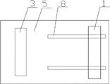
Fig. 1 is main TV structure schematic diagram of the present utility model;
Fig. 2 is the left view structural representation of Fig. 1;
Fig. 3 is the top view structural representation of Fig. 1.
The specific embodiment
see Fig. 1, Fig. 2, Fig. 3, it comprises chuck plate 1, be provided with the bayonet socket 2 that the shape and size with turbine head are complementary on chuck plate 1, it also comprises support plate 3, the cylinder block 4 of cylinder is anchored on the upper surface of base 5, the bottom surface of the fastening support plate 3 of cylinder arm 6 of cylinder, cylinder moves in vertical direction, worm gear to be locked is (not shown in FIG., belong to existing mature structure) turbine head be installed in corresponding bayonet socket 2, the middle part axle head of worm gear to be locked is supported on support plate 3, the locking end for the treatment of of worm gear to be locked exposes to support plate 3, the bottom of chuck plate 1 is provided with slide block 7, slide block 7 is flush-mounted in the rectilinear orbit 8 of base 5, rectilinear orbit 8 is perpendicular to the facade of chuck plate 1.
Claims (1)
1. a turbine is installed the auxiliary lock locking structure, it comprises chuck plate, be provided with the bayonet socket that the shape and size with turbine head are complementary on described chuck plate, it also comprises support plate, it is characterized in that: the cylinder block of cylinder is anchored on the upper surface of described base, the bottom surface of the fastening described support plate of cylinder arm of described cylinder, described cylinder moves in vertical direction, the turbine head of worm gear to be locked is installed in corresponding described bayonet socket, the middle part axle head of worm gear described to be locked is supported on described support plate, the locking end for the treatment of of worm gear described to be locked exposes to described support plate, the bottom of described chuck plate is provided with slide block, described slide block is flush-mounted in the rectilinear orbit of described base, described rectilinear orbit is perpendicular to the facade of described chuck plate.
Priority Applications (1)
| Application Number | Priority Date | Filing Date | Title |
|---|---|---|---|
| CN 201220615627 CN202985424U (en) | 2012-11-20 | 2012-11-20 | Auxiliary locking structure for installing turbine |
Applications Claiming Priority (1)
| Application Number | Priority Date | Filing Date | Title |
|---|---|---|---|
| CN 201220615627 CN202985424U (en) | 2012-11-20 | 2012-11-20 | Auxiliary locking structure for installing turbine |
Publications (1)
| Publication Number | Publication Date |
|---|---|
| CN202985424U true CN202985424U (en) | 2013-06-12 |
Family
ID=48556642
Family Applications (1)
| Application Number | Title | Priority Date | Filing Date |
|---|---|---|---|
| CN 201220615627 Expired - Fee Related CN202985424U (en) | 2012-11-20 | 2012-11-20 | Auxiliary locking structure for installing turbine |
Country Status (1)
| Country | Link |
|---|---|
| CN (1) | CN202985424U (en) |
-
2012
- 2012-11-20 CN CN 201220615627 patent/CN202985424U/en not_active Expired - Fee Related
Similar Documents
| Publication | Publication Date | Title |
|---|---|---|
| CN201736010U (en) | Nut tightening device for engine flywheel | |
| CN202660169U (en) | Adjustable-type centring foot | |
| CN202985424U (en) | Auxiliary locking structure for installing turbine | |
| CN202731514U (en) | Mounting structure of upper guide rail component with adjustable position | |
| CN201660370U (en) | Bi-directionally adjustable horizontal wheel device | |
| CN202985429U (en) | Auxiliary locking structure for installing turbine | |
| CN201315520Y (en) | Adjustable motor cabinet device | |
| CN202985423U (en) | Installation auxiliary locking structure of worm wheel | |
| CN202985421U (en) | Auxiliary locking device for installing turbine | |
| CN204334243U (en) | A kind of motor slot wheel press-fitting tool | |
| CN202985422U (en) | Auxiliary structure for installing turbine | |
| CN202985420U (en) | Auxiliary locking device for installing turbine | |
| CN202895072U (en) | Auxiliary installation structure for turbine locking | |
| CN203546545U (en) | Three-dimensional rail-adjusting device | |
| CN204819216U (en) | Intermittent gear manual clamping device | |
| CN201728608U (en) | Automobile rectifier bridge assembly clamp | |
| CN202895067U (en) | Auxiliary device for installing worm wheel sample pieces | |
| CN210260810U (en) | Glass clamping device for escalator | |
| CN103831759A (en) | Turbine installation auxiliary locking structure | |
| CN203212957U (en) | Accurate adjustment device for double-block type roadbed bent frame of ballastless track | |
| CN203022247U (en) | Solar bracket for trapezoidal roof tile | |
| CN202985428U (en) | Auxiliary structure for installing turbine | |
| CN202895068U (en) | Auxiliary structure for installing worm wheel sample pieces | |
| CN203712661U (en) | Heavy fixture and gauge platform adjusting device | |
| CN103628370A (en) | Three-dimensional rail adjusting device |
Legal Events
| Date | Code | Title | Description |
|---|---|---|---|
| C14 | Grant of patent or utility model | ||
| GR01 | Patent grant | ||
| CF01 | Termination of patent right due to non-payment of annual fee |
Granted publication date: 20130612 Termination date: 20151120 |
|
| EXPY | Termination of patent right or utility model |