CN202955665U - Electric lamp and lamp holder thereof - Google Patents
Electric lamp and lamp holder thereof Download PDFInfo
- Publication number
- CN202955665U CN202955665U CN2012206649981U CN201220664998U CN202955665U CN 202955665 U CN202955665 U CN 202955665U CN 2012206649981 U CN2012206649981 U CN 2012206649981U CN 201220664998 U CN201220664998 U CN 201220664998U CN 202955665 U CN202955665 U CN 202955665U
- Authority
- CN
- China
- Prior art keywords
- electric
- light
- conduction
- illuminator
- lamp socket
- Prior art date
- Legal status (The legal status is an assumption and is not a legal conclusion. Google has not performed a legal analysis and makes no representation as to the accuracy of the status listed.)
- Expired - Fee Related
Links
Images


Abstract
The utility model provides an electric lamp and a lamp holder thereof. The electric lamp comprises a luminous body and the lamp holder, wherein the lamp holder comprises a driving circuit board and a holder body, the driving circuit board is connected with the luminous body and comprises an electric conduction part and an electric conduction clamping part, the holder body comprises an electric conduction shell and an electric conduction fastener, the electric conduction part is connected with the electric conduction shell, and the electric conduction fastener is connected with the electric conduction clamping part.
Description
Technical field
The utility model relates to a kind of electric light, particularly a kind of electric light with lamp socket of being convenient to assembling.
Background technology
In modern's daily life, bulb is the practical lighting apparatus of an indispensability.Among the structure of general bulb, the lamp socket bottom is a wherein utmost point of circuit, and the metal shell around lamp socket is an other utmost point of circuit.In the manufacture process of bulb, must be in artificial mode, on lamp socket bottom and lamp socket metal shell on every side, the electric wire of burn-oning respectively, just can complete the circuit of bulb.
Yet the manufacture of artificial welding, can make time cost and human cost greatly promote; In addition, the yield of artificial welding is also unstable, and causes the keyholed back plate difficulty of technique yield to improve.
Therefore, be necessary to provide a kind of new bulb, its lamp socket has the structure of the assembling of being easy to.
The utility model content
Main purpose of the present utility model is to provide a kind of electric light with lamp socket of being convenient to assembling.
For reaching above-mentioned purpose, the utility model provides a kind of lamp socket, and in order to connect an illuminator, this lamp socket comprises:
The one drive circuit plate, in order to connect this illuminator, this drive circuit board comprises an electric-conductor and a conduction holding firmware; And
One pedestal comprises:
One external conductive casing, wherein this electric-conductor connects this external conductive casing; And
One conductive fasteners, in order to connect this conduction holding firmware.
Above-mentioned lamp socket, wherein this conductive fasteners connects this conduction holding firmware in the fixing mode.
Above-mentioned lamp socket, wherein this conduction holding firmware is a trip, this conductive fasteners is a projection.
Above-mentioned lamp socket, wherein this electric-conductor comprises an electroconductive elastic sheet.
Above-mentioned lamp socket, wherein this electric-conductor comprises an electroconductive elastic sheet.
Above-mentioned lamp socket, wherein this drive circuit board also comprises a plurality of conduction projections, and this illuminator also comprises a light-emitting component, and the plurality of conduction projection is in order to connect this light-emitting component.
Above-mentioned lamp socket, wherein this illuminator is a LED light lamp.
For reaching above-mentioned purpose, the utility model also provides a kind of electric light, and it comprises:
One illuminator; And
One lamp socket comprises:
The one drive circuit plate, connect this illuminator, and this drive circuit board comprises an electric-conductor and a conduction holding firmware; And
One pedestal comprises:
One external conductive casing, wherein this electric-conductor connects this external conductive casing; And
One conductive fasteners, in order to connect this conduction holding firmware.
Above-mentioned electric light, wherein this conductive fasteners connects this conduction holding firmware in the fixing mode.
Above-mentioned electric light, wherein this conduction holding firmware is a trip, this conductive fasteners is a projection.
Above-mentioned electric light, wherein this electric-conductor comprises an electroconductive elastic sheet.
Above-mentioned electric light, wherein this electric-conductor comprises an electroconductive elastic sheet.
Above-mentioned electric light, wherein this drive circuit board also comprises a plurality of conduction projections, and this illuminator also comprises a light-emitting component, and the plurality of conduction projection is in order to connect this light-emitting component.
Above-mentioned electric light, wherein this illuminator is a LED light lamp.
Below in conjunction with the drawings and specific embodiments, the utility model is described in detail, but not as to restriction of the present utility model.
The accompanying drawing explanation
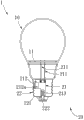
Fig. 1 is according to the schematic diagram of the electric light of an embodiment of the present utility model;
Fig. 2 is according to the cutaway view of the electric light of an embodiment of the present utility model;
Fig. 3 is according to the three-dimensional exploded view of the electric light of an embodiment of the present utility model;
Fig. 4 is according to the light-emitting component of an embodiment of the present utility model and the schematic diagram of drive circuit board.
Wherein, Reference numeral
Light-emitting component 11 light emitting diode 11a
Electroconductive elastic sheet 212a conducts electricity holding firmware 213
The specific embodiment
Below in conjunction with accompanying drawing, structural principle of the present utility model and operation principle are described in detail:
For above and other purpose of the present utility model, feature and advantage can be become apparent, cited below particularlyly go out specific embodiment of the utility model, and coordinate appended accompanying drawing, be described in detail below.
The following electric light about an embodiment of the present utility model referring to figs. 1 to Fig. 4 in the lump please.Fig. 1 is according to the schematic diagram of the electric light of an embodiment of the present utility model; Fig. 2 is according to the cutaway view of the electric light of an embodiment of the present utility model; Fig. 3 is according to the three-dimensional exploded view of the electric light of an embodiment of the present utility model; Fig. 4 is according to the light-emitting component of an embodiment of the present utility model and the schematic diagram of drive circuit board.
As shown in Figures 1 to 4, in an embodiment of the present utility model, electric light 1 comprises an illuminator 10 and a lamp socket 20.Illuminator 10 of the present utility model is a light emitting diode (Light Emitting Diode, LED) lamps, but the kind of illuminator of the present utility model 10 is not limited with LED light lamp, and it also can be incandescent lamp bulb or based on halogen bulb.Illuminator 10 comprises a light-emitting component 11, as shown in Figure 4, in embodiment of the present utility model, light-emitting component 11 for example can be a plurality of light emitting diode 11a and is embedded on a substrate 11b, substrate 11b is provided with a syndeton 11c, and syndeton 11c of the present utility model is a groups of slots; But the aspect of light-emitting component 11 is not limited with above-mentioned.Among this area, the illuminator 10 of electric light 1 is a prior art of extensively having been used, therefore do not repeat at this.
In embodiment of the present utility model, lamp socket 20 of the present utility model comprises one drive circuit plate 21 and a pedestal 22.Take illuminator 10 as a light emitting diode (Light Emitting Diode, LED) lamp be example, drive circuit board 21 of the present utility model comprises a rectifier, voltage-stablizer and transformer.Rectifier is in order to alternating current is converted to direct current, and transferring electric power is to illuminator 10.Voltage-stablizer is used so that voltage keeps stable.Transformer system is in order to change voltage and impedance.But the kind of drive circuit board 21 and function are not limited with above-mentioned.Drive circuit board 21 comprises two conduction projections 211, an electric-conductor 212 and a conduction holding firmware 213; Yet the quantity of conduction projection 211, an electric-conductor 212 and a conduction holding firmware 213 is not limited with above-mentioned, it can change to some extent according to design requirement.In the present embodiment, conduction projection 211 is that the groups of slots in order to the syndeton 11c with light-emitting component 11 is connected, with by electric power transfer to light-emitting component 11, make light emitting diode 11a emit beam.Electric-conductor 212 is in order to turning circuit, and it comprises an electroconductive elastic sheet 212a.In embodiment of the present utility model, conduction holding firmware 213 is one to have the trip (female joint with slot) of a slot.
When electric light 1 of the present utility model is assembled, only the conductive fasteners 222 of the conduction holding firmware 213 of drive circuit board 21 and pedestal 22 need be contacted and fixes, the electroconductive elastic sheet 212a of drive circuit board 21 can contact with external conductive casing 221; Then, then the light-emitting component of illuminator 10 11 is connected to the firmly conduction projection 211 of drive circuit board 21, can complete the assembling of electric light 1 of the present utility model.Therefore, by the structure of electric light 1 of the present utility model, can promptly with artificial or the mode of automation, assemble electric light 1, and save significantly time and the cost of assembling.
Certainly; the utility model also can have other various embodiments; in the situation that do not deviate from the utility model spirit and essence thereof; those of ordinary skill in the art are when making various corresponding changes and distortion according to the utility model, but these corresponding changes and distortion all should belong to the protection domain of the appended claim of the utility model.
Claims (14)
1. a lamp socket, in order to connect an illuminator, is characterized in that, this lamp socket comprises:
The one drive circuit plate, in order to connect this illuminator, this drive circuit board comprises an electric-conductor and a conduction holding firmware; And
One pedestal comprises:
One external conductive casing, wherein this electric-conductor connects this external conductive casing; And
One conductive fasteners, in order to connect this conduction holding firmware.
2. lamp socket according to claim 1, is characterized in that, this conductive fasteners connects this conduction holding firmware in the fixing mode.
3. lamp socket according to claim 2, is characterized in that, this conduction holding firmware is a trip, and this conductive fasteners is a projection.
4. lamp socket according to claim 2, is characterized in that, this electric-conductor comprises an electroconductive elastic sheet.
5. lamp socket according to claim 1, is characterized in that, this electric-conductor comprises an electroconductive elastic sheet.
6. according to claim 1,4 or 5 described lamp sockets, it is characterized in that, this drive circuit board also comprises a plurality of conduction projections, and this illuminator also comprises a light-emitting component, and the plurality of conduction projection is in order to connect this light-emitting component.
7. lamp socket according to claim 6, is characterized in that, this illuminator is a LED light lamp.
8. an electric light, is characterized in that, comprising:
One illuminator; And
One lamp socket comprises:
The one drive circuit plate, connect this illuminator, and this drive circuit board comprises an electric-conductor and a conduction holding firmware; And
One pedestal comprises:
One external conductive casing, wherein this electric-conductor connects this external conductive casing; And
One conductive fasteners, in order to connect this conduction holding firmware.
9. electric light according to claim 8, is characterized in that, this conductive fasteners connects this conduction holding firmware in the fixing mode.
10. electric light according to claim 9, is characterized in that, this conduction holding firmware is a trip, and this conductive fasteners is a projection.
11. electric light according to claim 9, is characterized in that, this electric-conductor comprises an electroconductive elastic sheet.
12. electric light according to claim 8, is characterized in that, this electric-conductor comprises an electroconductive elastic sheet.
13. according to Claim 8,11 or 12 described electric lights, is characterized in that, this drive circuit board also comprises a plurality of conduction projections, and this illuminator also comprises a light-emitting component, and the plurality of conduction projection is in order to connect this light-emitting component.
14. electric light according to claim 13, is characterized in that, this illuminator is a LED light lamp.
Priority Applications (1)
| Application Number | Priority Date | Filing Date | Title |
|---|---|---|---|
| CN2012206649981U CN202955665U (en) | 2012-12-05 | 2012-12-05 | Electric lamp and lamp holder thereof |
Applications Claiming Priority (1)
| Application Number | Priority Date | Filing Date | Title |
|---|---|---|---|
| CN2012206649981U CN202955665U (en) | 2012-12-05 | 2012-12-05 | Electric lamp and lamp holder thereof |
Publications (1)
| Publication Number | Publication Date |
|---|---|
| CN202955665U true CN202955665U (en) | 2013-05-29 |
Family
ID=48461235
Family Applications (1)
| Application Number | Title | Priority Date | Filing Date |
|---|---|---|---|
| CN2012206649981U Expired - Fee Related CN202955665U (en) | 2012-12-05 | 2012-12-05 | Electric lamp and lamp holder thereof |
Country Status (1)
| Country | Link |
|---|---|
| CN (1) | CN202955665U (en) |
Cited By (3)
| Publication number | Priority date | Publication date | Assignee | Title |
|---|---|---|---|---|
| CN103851572A (en) * | 2012-12-05 | 2014-06-11 | 王水妹 | Electric lamp and lamp holder thereof |
| CN103939770A (en) * | 2014-03-28 | 2014-07-23 | 立达信绿色照明股份有限公司 | Automatic assembling lamp head |
| CN104315380A (en) * | 2014-10-30 | 2015-01-28 | 江西奥其斯科技有限公司 | Full-automatic bulb lamp |
-
2012
- 2012-12-05 CN CN2012206649981U patent/CN202955665U/en not_active Expired - Fee Related
Cited By (4)
| Publication number | Priority date | Publication date | Assignee | Title |
|---|---|---|---|---|
| CN103851572A (en) * | 2012-12-05 | 2014-06-11 | 王水妹 | Electric lamp and lamp holder thereof |
| CN103939770A (en) * | 2014-03-28 | 2014-07-23 | 立达信绿色照明股份有限公司 | Automatic assembling lamp head |
| CN103939770B (en) * | 2014-03-28 | 2017-12-29 | 厦门立达信绿色照明集团有限公司 | Automatic assembling lamp holder |
| CN104315380A (en) * | 2014-10-30 | 2015-01-28 | 江西奥其斯科技有限公司 | Full-automatic bulb lamp |
Similar Documents
| Publication | Publication Date | Title |
|---|---|---|
| CN102155638A (en) | LED lighting device | |
| CN202955665U (en) | Electric lamp and lamp holder thereof | |
| WO2017024940A1 (en) | Electrical connection member | |
| CN204005417U (en) | A kind of plug-in type LED bulb lamp | |
| CN201983025U (en) | LED lamp and lamp body connecting structure thereof | |
| CN201772346U (en) | Non-electromagnetic radiation table lamp and adapter | |
| CN202915111U (en) | Light-emitting diode (LED) bulb with elastic conductive connection mechanism | |
| CN103851572A (en) | Electric lamp and lamp holder thereof | |
| CN204153612U (en) | A kind of shot-light modified node method | |
| CN207213991U (en) | A kind of LED lamp of driving power easy to assemble | |
| CN203404648U (en) | LED lamp | |
| CN202927540U (en) | Replaceable module combined type light-emitting diode (LED) lamp | |
| CN202852459U (en) | LED fluorescent lamp with external driving power supply | |
| CN205316117U (en) | LED fluorescent tube that can compatible electronic ballast | |
| TW201420937A (en) | Lamp and lamp holder thereof | |
| CN213452975U (en) | Ring type LED light-emitting module | |
| CN202992812U (en) | Cold light source type electronic bulb | |
| CN202349630U (en) | Light emitting diode lighting module and lamp with same | |
| CN202215987U (en) | Light emitting diode (LED) lighting lamp | |
| CN202065731U (en) | Energy-saving and durable candle lamp with light source composed of light-emitting diodes (LEDs) | |
| CN202216050U (en) | Assembled light-emitting diode (LED) daylight lamp | |
| CN201916758U (en) | Alternating current and direct current dual-purpose insertion connection light emitting diode (LED) lamp | |
| CN205402279U (en) | LED (light -emitting diode) integration module | |
| CN205331843U (en) | LED (light -emitting diode) lamp panel | |
| CN202392495U (en) | LED (light emitting diode) luminous module |
Legal Events
| Date | Code | Title | Description |
|---|---|---|---|
| C14 | Grant of patent or utility model | ||
| GR01 | Patent grant | ||
| CF01 | Termination of patent right due to non-payment of annual fee | ||
| CF01 | Termination of patent right due to non-payment of annual fee |
Granted publication date: 20130529 Termination date: 20161205 |