CN202955489U - Multifunctional electric torch - Google Patents
Multifunctional electric torch Download PDFInfo
- Publication number
- CN202955489U CN202955489U CN2012205601379U CN201220560137U CN202955489U CN 202955489 U CN202955489 U CN 202955489U CN 2012205601379 U CN2012205601379 U CN 2012205601379U CN 201220560137 U CN201220560137 U CN 201220560137U CN 202955489 U CN202955489 U CN 202955489U
- Authority
- CN
- China
- Prior art keywords
- pcb board
- camera
- electric torch
- multifunctional electric
- button
- Prior art date
- Legal status (The legal status is an assumption and is not a legal conclusion. Google has not performed a legal analysis and makes no representation as to the accuracy of the status listed.)
- Expired - Fee Related
Links
Images


Abstract
The utility model provides a multifunctional electric torch which comprises a shell, an electric torch switch, a battery set and an illuminating apparatus. The electric torch switch is arranged on the outer wall of the shell, the battery set is arranged in the shell, the illuminating apparatus is arranged at the front end of the inside of the shell, and a first PCB (printed circuit board) is arranged between the battery set and the illuminating apparatus and is electrically connected with the battery set and the illuminating apparatus; a camera is fixed onto the first PCB, and one end of the camera is connected onto a camera hole arranged on the illuminating apparatus; a display screen and a button assembly used for controlling the camera are further arranged on the outer wall of the shell; and a second PCB is disposed at the rear end of the inside of the shell and is electrically connected with the battery set, the camera, the display screen and the button assembly. The multifunctional electric torch has the advantages that the multifunctional electric torch is reasonable in structural design, functions of the camera and functions of a movable power source are added to functions of a common electric torch, and the various functions are integrated, so that the trouble that a user needs to carry a plurality of single products when going out is reduced, and the multiple functional products are integrated.
Description
Technical field
The utility model relates to the illuminations field, refers to especially multifunctional electric torch.
Background technology
Flashlight in the market is for each side effects limit such as cost or professional domains, all just possesses independent function, perhaps subsidiary function ratio is more single, such as: the market like product is mainly focused on profile or small and exquisite, but the function that does not possess photography, so can't meet long-time outdoor use, nor possess the function of portable power source.So, when these aspects demand is arranged, often need to buy several products simultaneously and could meet its instructions for use, therefore, need a kind of flashlight that simultaneously has a plurality of functions concurrently of exploitation.
The utility model content
The utility model proposes a kind of multifunctional electric torch, solved the single problem of the existing performance of flashlight in the prior art.
The technical solution of the utility model is achieved in that
A kind of multifunctional electric torch, comprise shell, be located at the torch switch on described outer shell outer wall, be located at the battery pack in described shell and the lighting device of being located at described enclosure front end, be provided with the first pcb board between described battery pack and described lighting device, described the first pcb board and described battery pack, described lighting device are electrically connected; Be fixed with a camera on described the first pcb board, an end of described camera is connected on the shooting hole that described lighting device offers; Described outer shell outer wall also is provided with display screen and for controlling the button assembly of described camera; Described enclosure rear end is provided with the second pcb board, and described the second pcb board and described battery pack, described camera, described display screen, described button assembly are electrically connected.
Preferably, described the second pcb board is fixed on the second pcb board cover that described enclosure rear end is provided with.
Further, described the second pcb board cover is provided with TF hole clipping, reset hole, DC socket and HD video delivery outlet, and described TF hole clipping, described reset hole, described DC socket, described HD video delivery outlet and described the second pcb board are electrically connected.
Preferably, described camera is fixed on described the first pcb board by a camera bracket and a camera locating rack.
Preferably, described the first pcb board, described battery pack and described the second pcb board cover are connected by a screw.
Preferably, also be provided with at least one handle on described shell.
Preferably, described lighting device comprises the lamp pearl, is arranged at the light cup of described lamp pearl periphery, is located at the torch eyeglass of described light cup front end and for the bung flange of fixing described light cup and described torch eyeglass.
Further, described lamp pearl is LED lamp pearl, and described lamp pearl and described light cup are uniform three of annular.
Preferably, described outer casing back is provided with a dust cap.
Preferably, described button assembly comprises the first button, the second button, the 3rd button, the 4th button and the 5th button be arranged in order.
The enforcement the beneficial effects of the utility model have:
Multifunctional electric torch of the present utility model is structurally reasonable in design, by increase the function of camera and portable power source on flashlight, the trouble that gathers together when minimizing is gone out and need to carry a plurality of single products by a plurality of functions, realize that multifunctional product is integrated.
The accompanying drawing explanation
In order to be illustrated more clearly in the utility model embodiment or technical scheme of the prior art, below will the accompanying drawing of required use in embodiment or description of the Prior Art be briefly described, apparently, accompanying drawing in the following describes is only embodiment more of the present utility model, for those of ordinary skills, under the prerequisite of not paying creative work, can also obtain according to these accompanying drawings other accompanying drawing.
The structural representation that Fig. 1 is an embodiment of the utility model;
The front sectional structure schematic diagram that Fig. 2 is Fig. 1 view;
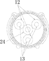
The A-A cross-sectional view that Fig. 3 is Fig. 1;
The C-C cross-sectional view that Fig. 4 is Fig. 1;
The D-D cross-sectional view that Fig. 5 is Fig. 1.
Figure number and explanation:
1, shell; 2, handle; 3, camera bracket; 4, torch switch; 5, the first button; 6, the second button; 7, the 3rd button; 8, the 4th button; 9, the 5th button; 10, the second pcb board; 11, torch eyeglass; 12, light cup; 13, lamp pearl; 14, screw; 15, the first pcb board; 16, battery pack; 17, the second pcb board cover; 18, dust cap; 19, display screen; 20, display screen cover; 21, camera locating rack; 22, camera; 23, bung flange; 24, shooting hole; 25, HD video delivery outlet; 26, TF hole clipping; 27, reset hole; 28, DC socket.
The specific embodiment
Below in conjunction with the accompanying drawing in the utility model embodiment, the technical scheme in the utility model embodiment is clearly and completely described, obviously, described embodiment is only the utility model part embodiment, rather than whole embodiment.Embodiment based in the utility model, those of ordinary skills are not making under the creative work prerequisite the every other embodiment obtained, and all belong to the scope of the utility model protection.
With reference to Fig. 1-Fig. 5, a kind of multifunctional electric torch, comprise shell 1, be located at the torch switch 4 on shell 1 outer wall, be located at the battery pack 16 in shell 1 and the lighting device of being located at shell 1 interior forward end, being provided with the first pcb board 15, the first pcb boards 15 between battery pack 16 and lighting device is electrically connected with battery pack 16, lighting device; Be fixed with a camera 22 on the first pcb board 15, an end of camera 22 is connected on the shooting hole 24 that lighting device offers; Shell 1 outer wall also is provided with display screen 19 and for controlling the button assembly of camera 22; The inner rear end of shell 1 is provided with the second pcb board 10, the second pcb boards 10 and is electrically connected with battery pack 16, camera 22, display screen 19, button assembly.Can realize the functions such as video recording, the data of taking pictures are processed, decoding output display by the second pcb board 10; the picture that can take or record a video by display screen 19 shows in real time; also be provided with a display screen cover 20 on display screen 19; display screen 19 can be fixed on shell 1; and by the display window locating and displaying out, protection display screen 19 is not damaged.By increasing on the structure of existing flashlight, can, for the camera 22 of taking and recording a video, can make flashlight can carry out the function of taking and recording a video.
The second pcb board 10 is fixed on the second pcb board cover 17 that the inner rear end of shell 1 is provided with, the second pcb board cover 17 is provided with TF hole clipping 26, reset hole 27, DC socket 28 and HD video delivery outlet 25, and TF hole clipping 26, reset hole 27, DC socket 28, HD video delivery outlet 25 and the second pcb board 10 are electrically connected.Can more firm the second pcb board 10 and the interface of TF hole clipping 26, reset hole 27, DC socket 28 and HD video delivery outlet 25 is exposed to the rear end of flashlight by the second pcb board cover 17, facilitate the operation of various functions.Can adjust according to the actual needs the position of TF hole clipping 26, reset hole 27, DC socket 28, HD video delivery outlet 25 and the second pcb board 10.Can external RAM card by TF hole clipping 26, can be used for photographed data storage and copy; Can be used for resetting of flashlight function by reset hole 27; Can be used as charging inlet and shell power output interface by DC seat 28; Can directly export high-definition signal to the broadcasting machines such as television set by HD video delivery outlet 25.
The first pcb board 15, battery pack 16 and the second pcb board cover 17 are connected by a screw 29, by screw 29, connect and can make inner all parts more firm.
Also be provided with at least one handle 2 on shell 1, preferred, handle 2 be symmetrical two, certainly, also can be arranged to according to the actual needs the quantity of needs, and is not limited to two of preferred embodiment.Portable when handle 2 can be for outdoor walking, also can be as hook, the used time can not hidden and be snapped in shell.
Lighting device comprises lamp pearl 13, be arranged at the light cup 12 of lamp pearl 13 peripheries, be located at the torch eyeglass 11 of light cup 12 front ends and for the bung flange 23 of fixed light cup 12 and torch eyeglass 11, preferably, lamp pearl 13 is LED lamp pearl, and lamp pearl 13 and light cup 12 are uniform three of annular.Certainly, lamp pearl 13 and light cup 12 can be also other quantity and spread geometry, and be not limited to uniform three of annular in preferred embodiment, the center of three lamp pearls 13 and three light cups 12 is shooting 24De position, hole, this position is located in shooting hole 24, both can facilitate the installation of camera 22, improve again its aesthetic appearance of flashlight.
Shell 1 rear end is provided with a dust cap 18, the flashlight rear end can be covered, both can dustproof and waterproof, can improve again its aesthetic appearance of flashlight.
Button assembly comprises the first button 5, the second button 6, the 3rd button 7, the 4th button 8 and the 5th button 9 be arranged in order.In operating process, the function that button is realized is as follows:
The first button 5: short-and-medium this key of pressing of standby or video process, can carry out number and amplify adjusting; In menu option, downward regulatory function key;
The second button 6: standby or video process are short in this button, can carry out number and dwindle adjusting; In menu option, the regulatory function key makes progress;
The 3rd button 7: menu button: short this key of pressing recalls function setting; The model selection button: long press this key can be making a video recording-take pictures-playback mode in switching mutually;
The 4th button 8: function is confirmed, starts, is suspended;
The 5th button 9: the long machine open/close of pressing.
Each function operation principle of complete machine is as follows:
The shooting of taking pictures: long by the 5th button 9 starts, insert the TF card, carry out functional mode selection and parameter setting with the 3rd button 7, camera 22 photographed datas are processed decoding output displays and storage data to the TF card through the second pcb board 10 data, by the first button 5, the second button 6, the 3rd button 7, the 4th button 8 and the 5th button 9, carry out various control operations;
File playback: length switches to playback function by the 3rd button 7, to take file chooses, can pass through the captured file of display screen 19 playback by the 4th button 8, also can data wire be connected to display device by HD video delivery outlet 25 and carry out file playback as television set etc., also the TF card can be extracted and insert card-reading apparatus file is play;
The torch illumination: repeatedly open torch switch 4, torch light is constantly switching under high light, the low light level, three kinds of states of SOS distress signal, opens torch and can carry out remote bat at night when taking night.
Portable power source: by DC socket 28 and external charging data wire, internal battery 16 is charged, with output patchcord output, other products is charged.
The foregoing is only preferred embodiment of the present utility model; not in order to limit the utility model; all within spirit of the present utility model and principle, any modification of doing, be equal to replacement, improvement etc., within all should being included in protection domain of the present utility model.
Claims (10)
1. a multifunctional electric torch, comprise shell, be located at the torch switch on described outer shell outer wall, be located at the battery pack in described shell and the lighting device of being located at described enclosure front end, it is characterized in that, be provided with the first pcb board between described battery pack and described lighting device, described the first pcb board and described battery pack, described lighting device are electrically connected; Be fixed with a camera on described the first pcb board, an end of described camera is connected on the shooting hole that described lighting device offers; Described outer shell outer wall also is provided with display screen and for controlling the button assembly of described camera; Described enclosure rear end is provided with the second pcb board, and described the second pcb board and described battery pack, described camera, described display screen, described button assembly are electrically connected.
2. multifunctional electric torch according to claim 1, is characterized in that, described the second pcb board is fixed on the second pcb board cover that described enclosure rear end is provided with.
3. multifunctional electric torch according to claim 2, it is characterized in that, described the second pcb board cover is provided with TF hole clipping, reset hole, DC socket and HD video delivery outlet, and described TF hole clipping, described reset hole, described DC socket, described HD video delivery outlet and described the second pcb board are electrically connected.
4. multifunctional electric torch according to claim 1, is characterized in that, described camera is fixed on described the first pcb board by a camera bracket and a camera locating rack.
5. multifunctional electric torch according to claim 2, is characterized in that, described the first pcb board, described battery pack and described the second pcb board cover are connected by a screw.
6. multifunctional electric torch according to claim 1, is characterized in that, also is provided with at least one handle on described shell.
7. multifunctional electric torch according to claim 1, is characterized in that, described lighting device comprises the lamp pearl, is arranged at the light cup of described lamp pearl periphery, is located at the torch eyeglass of described light cup front end and for the bung flange of fixing described light cup and described torch eyeglass.
8. multifunctional electric torch according to claim 7, is characterized in that, described lamp pearl is LED lamp pearl, and described lamp pearl and described light cup are uniform three of annular.
9. multifunctional electric torch according to claim 1, is characterized in that, described outer casing back is provided with a dust cap.
10. multifunctional electric torch according to claim 1, is characterized in that, described button assembly comprises the first button, the second button, the 3rd button, the 4th button and the 5th button be arranged in order.
Priority Applications (1)
| Application Number | Priority Date | Filing Date | Title |
|---|---|---|---|
| CN2012205601379U CN202955489U (en) | 2012-10-29 | 2012-10-29 | Multifunctional electric torch |
Applications Claiming Priority (1)
| Application Number | Priority Date | Filing Date | Title |
|---|---|---|---|
| CN2012205601379U CN202955489U (en) | 2012-10-29 | 2012-10-29 | Multifunctional electric torch |
Publications (1)
| Publication Number | Publication Date |
|---|---|
| CN202955489U true CN202955489U (en) | 2013-05-29 |
Family
ID=48461060
Family Applications (1)
| Application Number | Title | Priority Date | Filing Date |
|---|---|---|---|
| CN2012205601379U Expired - Fee Related CN202955489U (en) | 2012-10-29 | 2012-10-29 | Multifunctional electric torch |
Country Status (1)
| Country | Link |
|---|---|
| CN (1) | CN202955489U (en) |
Cited By (3)
| Publication number | Priority date | Publication date | Assignee | Title |
|---|---|---|---|---|
| CN104235623A (en) * | 2013-06-14 | 2014-12-24 | 深圳市海洋王照明工程有限公司 | Anti-explosion flashlight |
| CN104791614A (en) * | 2014-01-16 | 2015-07-22 | 深圳市海洋王照明工程有限公司 | Camera flashlight assembly |
| CN107925715A (en) * | 2015-09-07 | 2018-04-17 | 索尼公司 | Imaging device, its control method and program |
-
2012
- 2012-10-29 CN CN2012205601379U patent/CN202955489U/en not_active Expired - Fee Related
Cited By (6)
| Publication number | Priority date | Publication date | Assignee | Title |
|---|---|---|---|---|
| CN104235623A (en) * | 2013-06-14 | 2014-12-24 | 深圳市海洋王照明工程有限公司 | Anti-explosion flashlight |
| CN104791614A (en) * | 2014-01-16 | 2015-07-22 | 深圳市海洋王照明工程有限公司 | Camera flashlight assembly |
| CN107925715A (en) * | 2015-09-07 | 2018-04-17 | 索尼公司 | Imaging device, its control method and program |
| US10742884B2 (en) | 2015-09-07 | 2020-08-11 | Sony Corporation | Imaging device and control method |
| CN107925715B (en) * | 2015-09-07 | 2020-10-16 | 索尼公司 | Imaging apparatus, control method thereof, and program |
| US11477377B2 (en) | 2015-09-07 | 2022-10-18 | Sony Corporation | Imaging device and control method |
Similar Documents
| Publication | Publication Date | Title |
|---|---|---|
| CN205305032U (en) | Multi -functional spectral analysis STB | |
| CN202955489U (en) | Multifunctional electric torch | |
| CN106453711A (en) | Smart multi-surface touch phone | |
| CN102722068A (en) | Chargeable projector for mobile phone | |
| CN206055478U (en) | A kind of intelligent desk lamp | |
| CN202067072U (en) | Mobile phone projector | |
| CN202733459U (en) | Multifunctional flashlight | |
| CN203576127U (en) | Multifunctional photo frame | |
| CN204229618U (en) | Control the blue Tooth remote controller of mobile phone | |
| CN201479250U (en) | Digital camera with built-in wireless television remote vision function | |
| CN207353621U (en) | A kind of data cable of tangible control illumination | |
| CN202901856U (en) | Multi-functional flashlight | |
| CN107370911A (en) | A kind of instructor in broadcasting's duplex call system and the call handset with Tally indicator lamps | |
| CN209982568U (en) | Wireless network camera equipment capable of being charged circularly | |
| CN105914845A (en) | Multifunctional HUB with mobile power supply | |
| CN202818417U (en) | Multifunctional iPhone companion | |
| CN207460311U (en) | A kind of instructor in broadcasting's duplex call system and the call handset with Tally indicator lights | |
| CN202735659U (en) | Handset special-purpose projector with charging function | |
| CN210670474U (en) | Electronic terminal for social contact | |
| CN214507153U (en) | Mobile phone shell with turnable light supplement lamp and powered by mobile phone | |
| CN210609538U (en) | Multifunctional sound box | |
| CN211454202U (en) | Projector with wireless charging function | |
| CN204795470U (en) | Indoor audio player who has bluetooth electricity -saving lamp | |
| CN212565407U (en) | Multi-functional wisdom desk lamp | |
| CN219555017U (en) | Modularized intelligent terminal equipment |
Legal Events
| Date | Code | Title | Description |
|---|---|---|---|
| C14 | Grant of patent or utility model | ||
| GR01 | Patent grant | ||
| CF01 | Termination of patent right due to non-payment of annual fee |
Granted publication date: 20130529 Termination date: 20141029 |
|
| EXPY | Termination of patent right or utility model |