CN202953507U - Circular tube connected landing leg - Google Patents
Circular tube connected landing leg Download PDFInfo
- Publication number
- CN202953507U CN202953507U CN 201220657937 CN201220657937U CN202953507U CN 202953507 U CN202953507 U CN 202953507U CN 201220657937 CN201220657937 CN 201220657937 CN 201220657937 U CN201220657937 U CN 201220657937U CN 202953507 U CN202953507 U CN 202953507U
- Authority
- CN
- China
- Prior art keywords
- supports
- pillar
- connecting sleeves
- utility
- model
- Prior art date
- Legal status (The legal status is an assumption and is not a legal conclusion. Google has not performed a legal analysis and makes no representation as to the accuracy of the status listed.)
- Expired - Fee Related
Links
Images

Abstract
The utility model discloses a circular tube connected landing leg comprising supporting grooves, supports, connecting sleeves, a supporting beam and bottom slide plates. The supporting grooves are arranged in the upper parts of the supports; the supporting grooves are welded with the supports; the connecting sleeves are arranged in the middles of the supports; the connecting sleeves are welded with the supports; the two ends of the supporting beam are arranged in the connecting sleeves; the supporting beam is connected with the connecting sleeves through pin shafts; the bottom slide plates are arranged at the bottoms of the supports; and the bottom slide plates are welded with the supports. The circular tube connected landing leg disclosed by the utility model has the advantages of simple and reasonable structure, convenience for detachment, small occupied space, convenience for transportation and reduction of transportation cost, greatly reduces the working amount and the manufacturing cost, and saves the field installation time.
Description
Technical field
The utility model relates to a kind of pipe connection leg, is mainly used in belt conveyer.
Background technology
The carrier roller frame of belt conveyer is arranged on supporting leg, and supporting leg is the belt conveyer major part, refers to the weight in order to supporting container or equipment, and makes its support unit that is fixed in certain position, vibration and earthquake load in the time of also will bearing operation.Supporting leg comprises pillar, support beam and base, generally is welded structure, while constructing at the scene, because the supporting leg floor area is larger, to construction, has brought inconvenience.
Welded supporting leg, transportation is inconvenient, and processing technology is loaded down with trivial details, therefore novel rational in infrastructure, construction safety, easy to operate supporting leg is the inexorable trend of belt conveyer industry development.
Pipe connection leg of the present utility model, the occupation of land space is little, and convenient transportation, reduced traffic cost, and greatly reduced work capacity and cost of manufacture, saved field installation time.
Summary of the invention
The purpose of this utility model is to provide a kind of pipe connection leg.
The purpose of this utility model is achieved through the following technical solutions:
Pipe connection leg of the present utility model, comprise support slot, pillar, adapter sleeve, support beam and end slide plate.Support slot is located at pillar top, support slot and pillar welding, and adapter sleeve is located at the pillar middle part, adapter sleeve and pillar welding, the support beam two ends are located in adapter sleeve, and support beam is connected by bearing pin with adapter sleeve, end slide plate is located at a column bottom, end slide plate and pillar welding.
By above-mentioned the technical solution of the utility model, can be found out, pipe connection leg described in the utility model, simple and reasonable, convenient disassembly, the occupation of land space is little, convenient transportation, reduce traffic cost, and greatly reduced work capacity and cost of manufacture, saved field installation time.
The accompanying drawing explanation
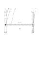
Fig. 1 is pipe connection leg structural representation;
Fig. 2 is pipe connection leg side-looking structural representation.
The specific embodiment
Pipe connection leg of the present utility model, its preferably the specific embodiment as shown in Figure 1 and Figure 2, the pipe connection leg comprises support slot 1, pillar 2, adapter sleeve 3, support beam 4 and end slide plate 5.
Support slot 1 is located at pillar 2 tops, support slot 1 and pillar 2 welding, and adapter sleeve 3 is located at pillar 2 middle parts, adapter sleeve 3 and pillar 2 welding, support beam 4 two ends are located in adapter sleeve 3, and support beam 4 is connected by bearing pin with adapter sleeve 3, end slide plate 5 is located at pillar 2 bottoms, end slide plate 5 and pillar 2 welding.
Pipe connection leg of the present utility model has following innovative point:
The support beam two ends of pipe connection leg are located in support sleeve, and support beam is connected by bearing pin with adapter sleeve, simple in structure, easy accessibility.
The beneficial effects of the utility model: simple and reasonable;
Convenient disassembly, the occupation of land space is little, and convenient transportation, reduced traffic cost;
And greatly reduce work capacity and cost of manufacture, saved field installation time.
The above; it is only the preferably specific embodiment of the utility model; but protection domain of the present utility model is not limited to this; anyly be familiar with those skilled in the art in the technical scope that the utility model discloses; the variation that can expect easily or replacement, within all should being encompassed in protection domain of the present utility model.
Claims (2)
1. a pipe connection leg, it is characterized in that, described pipe connection leg comprises support slot, pillar, adapter sleeve, support beam and end slide plate, described support slot is located at described pillar top, described support slot and the welding of described pillar, described adapter sleeve is located at described pillar middle part, described adapter sleeve and the welding of described pillar, slide plate of the described end is located at described column bottom, slide plate of the described end and the welding of described pillar.
2. pipe connection leg according to claim 1, is characterized in that, described support beam two ends are located in described adapter sleeve, and described support beam is connected by bearing pin with described adapter sleeve.
Priority Applications (1)
| Application Number | Priority Date | Filing Date | Title |
|---|---|---|---|
| CN 201220657937 CN202953507U (en) | 2012-12-04 | 2012-12-04 | Circular tube connected landing leg |
Applications Claiming Priority (1)
| Application Number | Priority Date | Filing Date | Title |
|---|---|---|---|
| CN 201220657937 CN202953507U (en) | 2012-12-04 | 2012-12-04 | Circular tube connected landing leg |
Publications (1)
| Publication Number | Publication Date |
|---|---|
| CN202953507U true CN202953507U (en) | 2013-05-29 |
Family
ID=48459090
Family Applications (1)
| Application Number | Title | Priority Date | Filing Date |
|---|---|---|---|
| CN 201220657937 Expired - Fee Related CN202953507U (en) | 2012-12-04 | 2012-12-04 | Circular tube connected landing leg |
Country Status (1)
| Country | Link |
|---|---|
| CN (1) | CN202953507U (en) |
Cited By (3)
| Publication number | Priority date | Publication date | Assignee | Title |
|---|---|---|---|---|
| CN103612877A (en) * | 2012-12-04 | 2014-03-05 | 力博重工科技股份有限公司 | Circular tube connecting supporting leg |
| CN104235571A (en) * | 2013-06-20 | 2014-12-24 | 国家电网公司 | Operation table for insulation porcelain cleaning |
| CN105065174A (en) * | 2015-09-08 | 2015-11-18 | 常州液压成套设备厂有限公司 | Detachable servomotor connecting rod |
-
2012
- 2012-12-04 CN CN 201220657937 patent/CN202953507U/en not_active Expired - Fee Related
Cited By (3)
| Publication number | Priority date | Publication date | Assignee | Title |
|---|---|---|---|---|
| CN103612877A (en) * | 2012-12-04 | 2014-03-05 | 力博重工科技股份有限公司 | Circular tube connecting supporting leg |
| CN104235571A (en) * | 2013-06-20 | 2014-12-24 | 国家电网公司 | Operation table for insulation porcelain cleaning |
| CN105065174A (en) * | 2015-09-08 | 2015-11-18 | 常州液压成套设备厂有限公司 | Detachable servomotor connecting rod |
Similar Documents
| Publication | Publication Date | Title |
|---|---|---|
| CN202953507U (en) | Circular tube connected landing leg | |
| CN103612247A (en) | Cabinet frame turnover worktable | |
| CN203579525U (en) | Docking frame vehicle suitable for long and thin cabin section products | |
| CN202953431U (en) | U-shaped plate connecting landing leg | |
| CN202953506U (en) | Connecting support leg of blocking joint | |
| CN102431904A (en) | Rotary crane | |
| CN203357363U (en) | Strut type jig frame used for body section manufacturing | |
| CN103612877A (en) | Circular tube connecting supporting leg | |
| CN103101043A (en) | Movable tool table and using method thereof | |
| CN103587895A (en) | U-shaped board connection support leg | |
| CN203332640U (en) | Movable cotton yarn bracket | |
| CN103600971A (en) | Clamping type connector connecting leg | |
| CN204587835U (en) | A kind of coal machine backplate arranging apparatus | |
| CN203079586U (en) | Novel arm line type crane | |
| CN202831240U (en) | Box-section column splicing mechanism | |
| CN202384699U (en) | Suspension supporting device for replacing overhead ground wire | |
| CN203653142U (en) | Transformer hoisting conveying device | |
| CN202544097U (en) | Strut intermediate mechanism for steel structure building | |
| CN202953429U (en) | Novel simple and easy deep slot roller supporting frame | |
| CN202788595U (en) | Movable crawling ladder | |
| CN201645477U (en) | Mobile track tool car | |
| CN202465079U (en) | Ultralow-altitude hoist trolley | |
| CN202831245U (en) | Purlin base fixing mechanism | |
| CN202831244U (en) | Expanding brace mechanism used for foundation steel structure | |
| CN202023253U (en) | Vestibule support mechanism for steel structure |
Legal Events
| Date | Code | Title | Description |
|---|---|---|---|
| C14 | Grant of patent or utility model | ||
| GR01 | Patent grant | ||
| CF01 | Termination of patent right due to non-payment of annual fee | ||
| CF01 | Termination of patent right due to non-payment of annual fee |
Granted publication date: 20130529 Termination date: 20181204 |