CN202910194U - Roll ball sleeve - Google Patents
Roll ball sleeve Download PDFInfo
- Publication number
- CN202910194U CN202910194U CN 201220564853 CN201220564853U CN202910194U CN 202910194 U CN202910194 U CN 202910194U CN 201220564853 CN201220564853 CN 201220564853 CN 201220564853 U CN201220564853 U CN 201220564853U CN 202910194 U CN202910194 U CN 202910194U
- Authority
- CN
- China
- Prior art keywords
- ball sleeve
- roll
- roll ball
- sleeve
- ball
- Prior art date
- Legal status (The legal status is an assumption and is not a legal conclusion. Google has not performed a legal analysis and makes no representation as to the accuracy of the status listed.)
- Expired - Fee Related
Links
Images
Abstract
The utility model discloses a roll ball sleeve. The roll ball sleeve comprises a roll sleeve body. The roll ball sleeve is in a cylindrical shape. A spiral groove is arranged on the inner wall surface of the roll ball sleeve, a plurality of roll balls are movably arranged inside the spiral groove. The roll ball sleeve has the advantages of being reasonable in structure, and ingenious in design. A steel ball is in a spiral movement in the roll ball sleeve when stamping equipment moves up and down so that the roll ball sleeve prevents the stamping equipment from shocking while moving up and down, the resistance is reduced, and the service life of the product is prolonged.
Description
Technical field
The utility model relates to pressing equipment, particularly a kind of ball sleeve for pressing equipment.
Background technology
In the prior art, generally in pressing equipment, all can be applied to ball sleeve, steel ball generally all is that the layering annular is arranged on the same level height and position in the existing ball sleeve, use the pressing equipment of ball sleeve when moving up and down, a circle steel ball is pressed into simultaneously by lining often, also has simultaneously a circle steel ball to be deviate from.When steel ball is deviate from or be pressed into lining, can produce vibrations, and resistance is larger, causes the life-span of product shorter.
Summary of the invention
The purpose of this utility model is, for the problems referred to above, provides a kind of ball sleeve reasonable in design, thereby can avoid pressing equipment to produce vibrations when moving up and down, and reduces resistance, prolongs the service life of product.
The technical scheme that the utility model adopts for achieving the above object is:
A kind of ball sleeve, it comprises a ball sleeve body, this ball sleeve is cylindric, is provided with a helical groove in the internal face of this ball sleeve, is provided with movably some balls in this helical groove.
Described helical groove is extended toward the lower end by the upper end of this ball sleeve internal face.
The two ends of this ball sleeve internal face are respectively equipped with a cannelure.
The beneficial effects of the utility model are: the utility model is rational in infrastructure, design ingenious, when pressing equipment moves up and down steel ball in ball sleeve corkscrew motion, thereby can avoid pressing equipment when moving up and down, to produce vibrations, and the minimizing resistance, the service life of prolongation product.
Below in conjunction with accompanying drawing and embodiment, the utility model is further specified.
Description of drawings
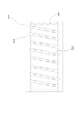
Fig. 1 is structural representation of the present utility model.
The specific embodiment
Embodiment: see Fig. 1, a kind of ball sleeve of the utility model, it comprises a ball sleeve body 1, this ball sleeve is cylindric, is provided with a helical groove 2 in the internal face of this ball sleeve, is provided with movably some balls 3 in this helical groove 2.
Described helical groove 2 is extended toward the lower end by the upper end of these ball 3 cover internal faces.
The two ends of these ball 3 cover internal faces are respectively equipped with a cannelure 4.
The utility model is rational in infrastructure, designs ingeniously, and steel ball is corkscrew motion in ball 3 cover when pressing equipment moves up and down, thereby can avoid pressing equipment to produce vibrations when moving up and down, and the minimizing resistance, the service life of prolongation product.
As described in the utility model embodiment, with other ball 3 covers of the same or similar structure of the utility model, all in the utility model protection domain.
Claims (3)
1. ball sleeve, it is characterized in that: it comprises a ball sleeve body, this ball sleeve is cylindric, is provided with a helical groove in the internal face of this ball sleeve, is provided with movably some balls in this helical groove.
2. ball sleeve according to claim 1 is characterized in that, described helical groove is extended toward the lower end by the upper end of this ball sleeve internal face.
3. ball sleeve according to claim 1 is characterized in that, the two ends of this ball sleeve internal face are respectively equipped with a cannelure.
Priority Applications (1)
| Application Number | Priority Date | Filing Date | Title |
|---|---|---|---|
| CN 201220564853 CN202910194U (en) | 2012-10-31 | 2012-10-31 | Roll ball sleeve |
Applications Claiming Priority (1)
| Application Number | Priority Date | Filing Date | Title |
|---|---|---|---|
| CN 201220564853 CN202910194U (en) | 2012-10-31 | 2012-10-31 | Roll ball sleeve |
Publications (1)
| Publication Number | Publication Date |
|---|---|
| CN202910194U true CN202910194U (en) | 2013-05-01 |
Family
ID=48158540
Family Applications (1)
| Application Number | Title | Priority Date | Filing Date |
|---|---|---|---|
| CN 201220564853 Expired - Fee Related CN202910194U (en) | 2012-10-31 | 2012-10-31 | Roll ball sleeve |
Country Status (1)
| Country | Link |
|---|---|
| CN (1) | CN202910194U (en) |
Cited By (1)
| Publication number | Priority date | Publication date | Assignee | Title |
|---|---|---|---|---|
| CN103464617A (en) * | 2013-09-02 | 2013-12-25 | 昆山旭龙精密机械有限公司 | Guide column component |
-
2012
- 2012-10-31 CN CN 201220564853 patent/CN202910194U/en not_active Expired - Fee Related
Cited By (1)
| Publication number | Priority date | Publication date | Assignee | Title |
|---|---|---|---|---|
| CN103464617A (en) * | 2013-09-02 | 2013-12-25 | 昆山旭龙精密机械有限公司 | Guide column component |
Similar Documents
| Publication | Publication Date | Title |
|---|---|---|
| CN203348303U (en) | Rapid locking structure for ball head | |
| CN202725840U (en) | Guide pillar for mold | |
| CN202910194U (en) | Roll ball sleeve | |
| CN204396572U (en) | A kind of dome turns over assistor | |
| CN203593576U (en) | Leading screw jack | |
| CN202778506U (en) | Activated carbon adsorption block | |
| CN208305872U (en) | Two-level spring compression sleeve | |
| CN204264724U (en) | A kind of tank car Novel tank body structure | |
| CN202116280U (en) | Telescopic hopper | |
| CN202391911U (en) | Chemical bolt | |
| CN202946653U (en) | Seal blocking cover resistant to high pressure | |
| CN202365641U (en) | Oil-saving pan capable of being vertically placed | |
| CN203016369U (en) | Liftable domestic bed | |
| CN203404590U (en) | Steel ball seat structure | |
| CN202965751U (en) | Pen container with sucker | |
| CN202783362U (en) | Tie rod left-right connector assembly | |
| CN201704707U (en) | Well cover mechanism for straight buried pipeline | |
| CN203127504U (en) | Steel strip coil storage rubber pad | |
| CN202923897U (en) | Top cover of filling machine | |
| CN203189470U (en) | Head bolt of specially-manufactured thread mechanism of tube making machine | |
| CN204005088U (en) | Household electric appliance leg rubber pad | |
| CN202451042U (en) | Metal ladder crosspiece | |
| CN202900890U (en) | Anti-skid hook type nail | |
| CN202170993U (en) | Piston with lubricating oil grooves | |
| CN202963079U (en) | Thimble on nut fastening clip of tubing machine |
Legal Events
| Date | Code | Title | Description |
|---|---|---|---|
| C14 | Grant of patent or utility model | ||
| GR01 | Patent grant | ||
| CF01 | Termination of patent right due to non-payment of annual fee |
Granted publication date: 20130501 Termination date: 20141031 |
|
| EXPY | Termination of patent right or utility model |