CN202884095U - Friction-free ball valve based on Geneva mechanism - Google Patents
Friction-free ball valve based on Geneva mechanism Download PDFInfo
- Publication number
- CN202884095U CN202884095U CN 201220528309 CN201220528309U CN202884095U CN 202884095 U CN202884095 U CN 202884095U CN 201220528309 CN201220528309 CN 201220528309 CN 201220528309 U CN201220528309 U CN 201220528309U CN 202884095 U CN202884095 U CN 202884095U
- Authority
- CN
- China
- Prior art keywords
- valve
- driven sheave
- ball
- pivoted arm
- driven
- Prior art date
- Legal status (The legal status is an assumption and is not a legal conclusion. Google has not performed a legal analysis and makes no representation as to the accuracy of the status listed.)
- Expired - Fee Related
Links
Images


Landscapes
- Mechanically-Actuated Valves (AREA)
Abstract
The utility model discloses a friction-free ball valve based on a Geneva mechanism. The friction-free ball valve comprises a valve body, a valve ball, a valve seat and a support seat. The ball valve further comprises a driving drive plate, a first driven Geneva wheel and a second driven Geneva wheel. The driving drive plate is matched with the first driven Geneva wheel and the second driven Geneva wheel to form the external meshing Geneva mechanism. A drive rod is coaxially arranged on one side of the first driven Geneva wheel. Two clamp feet are arranged on one side of the second driven Geneva wheel. The two clamp feet of the second driven Geneva wheel are clamped in two L-shaped grooves of the valve ball. The eccentric section of the drive rod is clamped into a key groove of the valve ball. The driving drive plate comprises a notch circular disc, a first rotating arm and a second rotating arm. The first rotating arm and the second rotating arm are arranged on one side of the notch circular disc along the radial direction of the notch circular disc. The first rotating arm is meshed with the first driven Geneva wheel and the second driven Geneva wheel through cylindrical pins on the upper side and the lower side of the first rotating arm. According to the friction-free ball valve, an intermittent drive mode is used, rotating-inclining step-by-step movement of the valve ball is achieved, structure is simple, and the friction-free ball valve is suitable for volume production so that cost is lowered.
Description
Technical field
The utility model relates to a kind of ball valve, relates in particular to a kind of nothing friction ball valve based on Geneva mechanism.
Background technique
At present, known ball valve generally adopts the structure of valve ball pre-pressing sealing surface of seat, realizes opening and closing of valve by direct rotation valve ball, and its shortcoming is because valve seal needs certain pretightening force, therefore it is larger to open and close required moment, the wearing and tearing of valve ball and valve seat are also larger.
ZL200720082066.5 discloses a kind of low torque ball valve, when being characterized in that this ball valve valve ball rotates with sealing surface of seat without friction, when valve closing, contact, and valve rod only rotates, frictional force is little, and required moment is little, is convenient to sealing, but the structure component that the substep of realizing valve ball rotation-inclination moves are more, assembling is complicated, and required precision is higher, and difficulty of processing is larger, be unfavorable for batch production, thereby so that cost is higher.
The model utility content
For the prior art above shortcomings, the purpose of this utility model just is to provide a kind of nothing friction ball valve based on Geneva mechanism, adopt the mode of intermittently-driving, the rotation of realization valve ball-inclination substep motion, structure is simpler, processing is more prone to, and is more suitable for batch production, makes cost.
To achieve these goals, the technical solution adopted in the utility model is such: a kind of nothing friction ball valve based on Geneva mechanism, comprise valve body, valve ball, valve seat and supporting base, described valve ball is the spheroid with through hole, be positioned at valve body, its through hole axially and valve body axial consistent, the top of valve ball has a keyway, have L shaped draw-in groove in the both sides of keyway, angle between two L shaped draw-in grooves and the keyway is 90 °, have a blind hole in the valve ball bottom, the bottom of valve body and blind hole corresponding position are provided with a cylinder boss, and described valve ball cooperates with cylinder boss by blind hole with valve body and links to each other; Described supporting base is a disk-like structure, valve body above valve ball have one with the mounting hole of supporting base coupling, supporting base cooperates with valve body by this mounting hole and links to each other, it is characterized in that, also comprise initiatively driver plate, the first driven sheave and the second driven sheave, described active driver plate cooperates the formation Sheave Device with the External Gear with the first driven sheave and the second driven sheave;
Wherein, one side of the first driven sheave is coaxially arranged with a driving lever, this driving lever is eccentric driving lever, driving lever has eccentric segment away from an end of the first driven sheave, the middle part of the second driven sheave has a through hole that driving lever is passed, side at the second driven sheave also is provided with two card bases, the bottom of supporting base has a circular hole, two card bases of the second driven sheave are stuck in the two L shaped grooves of valve ball after this circular hole passes, its eccentric segment snapped in the keyway on the valve ball after described driving lever passed from the through hole of the second driven sheave, and the first driven sheave and the second driven sheave are set up in parallel up and down;
Described active driver plate comprises a cutaway disk and radially is arranged on the first pivoted arm and second pivoted arm of cutaway disk one side along cutaway disk, and wherein, the first pivoted arm stretches out from the breach middle part of cutaway disk, and the angle between the second pivoted arm and the first pivoted arm is 90 °; Be provided with the circumference pin at the first pivoted arm away from the up and down both sides of an end of cutaway disk, the second pivoted arm is provided with the circumference pin away from the upside of an end of cutaway disk; The first pivoted arm by its up and down the straight pin of both sides be meshed with the second driven sheave with the first driven sheave simultaneously and be in the same place.
Further, also be provided with a reducing gear above supporting base, described active driver plate is driven by reducing gear.
When valve closes valve, driving reducing gear by motor or handle rotates, reducing gear drives initiatively driver plate again, driving the first pivoted arm by the active driver plate again rotates towards a side that deviates from the second pivoted arm, this moment, the first pivoted arm drove the first driven sheave and the second driven sheave rotates synchronously, the first driven sheave and the second driven sheave are without relative movement at this moment, and the card base of the first driven sheave drives valve ball and rotatablely moves around vertical center line along valve ball; After the active driver plate turns over 90 degree, the straight pin of the first pivoted arm and the first driven sheave and the second driven sheave break away from, simultaneously, straight pin on the second pivoted arm and the engagement of the first driven sheave, because the second pivoted arm only upside has straight pin, the second pivoted arm drove the first driven sheave and was rotated further this moment, and the second driven sheave no longer rotates, be that valve ball no longer rotates and driven to tilt take the valve body cylinder boss as fulcrum to valve seat by the eccentric driving lever of the first driven sheave, press to valve seat and form sealing surface, thereby realize sealing.
During valve opening, drive the reducing gear backward rotation by motor or handle, reducing gear drives initiatively driver plate again, driving the second pivoted arm by the active driver plate again rotates towards a side that deviates from the first pivoted arm, at first the second pivoted arm drives the first driven sheave and compares backward rotation with closing the valve process, and this moment, the second driven sheave kept motionless; After the active driver plate turns over 90 °, the the first pivoted arm up and down straight pin of both sides meshes with the first driven sheave and the second driven sheave again, rotate synchronously together thereby drive the first driven sheave and the second driven sheave, the also counterrotating of valve ball this moment is until valve open.
When the second pivoted arm drives the rotation of the second driven sheave, initiatively the not barbed portion of driver plate enters the indent curved portion of the second driven sheave, when valve ball forms sealing because inclination makes valve ball contact with valve seat, after ball valve is closed, if artificial backward rotation valve ball, and the second driven sheave connects with valve ball, then make the second driven sheave form driving wheel, but because the second driven sheave has indent, and initiatively the not barbed portion of driver plate is positioned at the female parts of the second driven sheave, so that the female parts of the second driven sheave has been blocked by the not barbed portion of active driver plate, thereby the second driven sheave can't be rotated, and then the formation self-locking, so that this ball valve can not be opened by stirring valve ball.
Compared with prior art, the beneficial effects of the utility model are:
Simple in structure, valve ball does not contact all the time with the sealing joint face during along vertical center line rotation, only tilts to press to sealing surface when closing, because valve ball and sealing surface without rotating relative to contacting, have reduced the frictional force of valve ball greatly, has greatly reduced wearing and tearing yet; When valve ball is in closed condition, the female parts of the second driven sheave and the initiatively not barbed portion engagement of driver plate, this moment, external force was stirred valve ball, can't make the valve ball rotation, made valve have self-lock ability; The key component of the whole winding machine rotation-substep motion of tilting is made of Sheave Device with the External Gear, and structure is very simple, the assembling of being more convenient for, processing, thereby be suitable for batch production, make cost cheaper.
Description of drawings
Fig. 1 is longitudinal sectional view of the present utility model;
Fig. 2 is the plan view of valve ball;
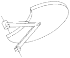
Fig. 3 is the structural representation of active driver plate;
Fig. 4 is the structural representation of the first driven sheave;
Fig. 5 is the structural representation of the second driven sheave;
Fig. 6 is the plan view when initiatively driver plate cooperates with the first driven sheave and the second driven sheave.
Embodiment
The utility model is described in further detail below in conjunction with drawings and Examples.
Embodiment: referring to Fig. 1 to Fig. 6, a kind of nothing friction ball valve based on Geneva mechanism, comprise valve body 1, valve ball 2, valve seat 3 and supporting base 4, described valve ball 2 is the spheroid with through hole, be positioned at valve body 1, its through hole axially and valve body 1 axial consistent, the top of valve ball 2 has a keyway, have L shaped draw-in groove in the both sides of keyway, angle between two L shaped draw-in grooves and the keyway is 90 °, have a blind hole in valve ball 2 bottoms, the bottom of valve body 1 and blind hole corresponding position are provided with a cylinder boss, and described valve ball 2 cooperates with cylinder boss by blind hole with valve body 1 and links to each other; Described supporting base 4 is a disk-like structure, the valve body 1 above valve ball 2 have one with the mounting hole of supporting base 4 coupling, supporting base 4 cooperates with valve body 1 by this mounting hole and links to each other.
Also comprise initiatively driver plate 7, the first driven sheave 6 and the second driven sheave 5, described active driver plate 7 cooperates the formation Sheave Device with the External Gear with the first driven sheave 6 and the second driven sheave 5.
Wherein, one side of the first driven sheave 6 is coaxially arranged with a driving lever, this driving lever is eccentric driving lever, driving lever has eccentric segment away from an end of the first driven sheave 6, the middle part of the second driven sheave 5 has a through hole that driving lever is passed, side at the second driven sheave 5 also is provided with two card bases, the bottom of supporting base 4 has a circular hole, two card bases of the second driven sheave 5 are stuck in the two L shaped grooves of valve ball 2 after this circular hole passes, its eccentric segment snapped in the keyway on the valve ball 2 after described driving lever passed from the through hole of the second driven sheave 5, and the first driven sheave 6 and the second driven sheave 5 are set up in parallel up and down.Also be provided with a reducing gear 8 above supporting base 4, described active driver plate 7 is driven by reducing gear 8.
Described active driver plate 7 comprises a cutaway disk (edge of described breach is circular arc) and radially is arranged on the first pivoted arm and second pivoted arm of cutaway disk one side along cutaway disk, wherein, the first pivoted arm stretches out from the breach middle part of cutaway disk, and the angle between the second pivoted arm and the first pivoted arm is 90 °; Be provided with the circumference pin at the first pivoted arm away from the up and down both sides of an end of cutaway disk, the second pivoted arm is provided with the circumference pin away from the upside of an end of cutaway disk; The first pivoted arm by its up and down the straight pin of both sides be meshed with the second driven sheave 5 with the first driven sheave 6 simultaneously and be in the same place.
When valve closes valve, driving reducing gear 8 by motor or handle rotates, reducing gear 8 drives initiatively driver plate 7 again, driving the first pivoted arm by active driver plate 7 again rotates towards a side that deviates from the second pivoted arm, this moment, the first pivoted arm drove the first driven sheave 6 and the second driven sheave 5 rotates synchronously, the first driven sheave 6 and the second driven sheave 5 are without relative movement at this moment, and the card base of the first driven sheave 6 drives valve ball 2 and rotatablely moves around vertical center line along valve ball 2; After active driver plate 7 turns over 90 degree, the straight pin of the first pivoted arm and the first driven sheave 6 and the second driven sheave 5 break away from, simultaneously, straight pin on the second pivoted arm and 6 engagements of the first driven sheave, because the second pivoted arm only upside has straight pin, the second pivoted arm drove the first driven sheave 6 and was rotated further this moment, and the second driven sheave 5 no longer rotates, be that valve ball 2 no longer rotates and driven take valve body 1 cylinder boss 3 to tilt as fulcrum to valve seat by the eccentric driving lever of the first driven sheave 6, press to valve seat 3 and form sealing surface, thereby realize sealing.
During valve opening, drive reducing gear 8 backward rotation by motor or handle, reducing gear 8 drives initiatively driver plate 7 again, driving the second pivoted arm by active driver plate 7 again rotates towards a side that deviates from the first pivoted arm, at first the second pivoted arm drives the first driven sheave 6 and compares backward rotation with closing the valve process, and this moment second, driven sheave 5 kept motionless; After active driver plate 7 turns over 90 °, the the first pivoted arm up and down straight pin of both sides meshes with the first driven sheave 6 and the second driven sheave 5 again, rotate synchronously together thereby drive the first driven sheave 6 and the second driven sheave 5, the also counterrotating of valve ball 2 this moment is until valve open.
When the second pivoted arm drives 5 rotation of the second driven sheave, initiatively the not barbed portion of driver plate 7 enters the indent curved portion of the second driven sheave 5, when valve ball 2 forms sealing because inclination makes valve ball 2 contact with valve seat 3, after ball valve is closed, if artificial backward rotation valve ball 2, and the second driven sheave 5 is to connect with valve ball 2, then make the second driven sheave 5 form driving wheel, but because the second driven sheave 5 has indent, and initiatively the not barbed portion of driver plate 7 is positioned at the female parts of the second driven sheave 5, so that the female parts of the second driven sheave 5 has been blocked by the not barbed portion of active driver plate 7, thereby the second driven sheave 5 can't be rotated, and then the formation self-locking, so that this ball valve can not be opened by stirring valve ball 2.
Need to prove at last, above embodiment is only in order to the technical solution of the utility model to be described but not the restriction technologies scheme, although the claimant has been described in detail the utility model with reference to preferred embodiment, those of ordinary skill in the art is to be understood that, those are made amendment to the technical solution of the utility model or are equal to replacement, and do not break away from aim and the scope of the technical program, all should be encompassed in the middle of the claim scope of the present utility model.
Claims (2)
- One kind based on Geneva mechanism without the friction ball valve, comprise valve body, valve ball, valve seat and supporting base, described valve ball is the spheroid with through hole, be positioned at valve body, its through hole axially and valve body axial consistent, the top of valve ball has a keyway, have L shaped draw-in groove in the both sides of keyway, angle between two L shaped draw-in grooves and the keyway is 90 °, have a blind hole in the valve ball bottom, the bottom of valve body and blind hole corresponding position are provided with a cylinder boss, and described valve ball cooperates with cylinder boss by blind hole with valve body and links to each other; Described supporting base is a disk-like structure, valve body above valve ball have one with the mounting hole of supporting base coupling, supporting base cooperates with valve body by this mounting hole and links to each other, it is characterized in that, also comprise initiatively driver plate, the first driven sheave and the second driven sheave, described active driver plate cooperates the formation Sheave Device with the External Gear with the first driven sheave and the second driven sheave;Wherein, one side of the first driven sheave is coaxially arranged with a driving lever, this driving lever is eccentric driving lever, driving lever has eccentric segment away from an end of the first driven sheave, the middle part of the second driven sheave has a through hole that driving lever is passed, side at the second driven sheave also is provided with two card bases, the bottom of supporting base has a circular hole, two card bases of the second driven sheave are stuck in the two L shaped grooves of valve ball after this circular hole passes, its eccentric segment snapped in the keyway on the valve ball after described driving lever passed from the through hole of the second driven sheave, and the first driven sheave and the second driven sheave are set up in parallel up and down;Described active driver plate comprises a cutaway disk and radially is arranged on the first pivoted arm and second pivoted arm of cutaway disk one side along cutaway disk, and wherein, the first pivoted arm stretches out from the breach middle part of cutaway disk, and the angle between the second pivoted arm and the first pivoted arm is 90 °; Be provided with the circumference pin at the first pivoted arm away from the up and down both sides of an end of cutaway disk, the second pivoted arm is provided with the circumference pin away from the upside of an end of cutaway disk; The first pivoted arm by its up and down the straight pin of both sides be meshed with the second driven sheave with the first driven sheave simultaneously and be in the same place.
- 2. a kind of nothing friction ball valve based on Geneva mechanism according to claim 1 is characterized in that, also be provided with a reducing gear above supporting base, described active driver plate is driven by reducing gear.
Priority Applications (1)
| Application Number | Priority Date | Filing Date | Title |
|---|---|---|---|
| CN 201220528309 CN202884095U (en) | 2012-10-16 | 2012-10-16 | Friction-free ball valve based on Geneva mechanism |
Applications Claiming Priority (1)
| Application Number | Priority Date | Filing Date | Title |
|---|---|---|---|
| CN 201220528309 CN202884095U (en) | 2012-10-16 | 2012-10-16 | Friction-free ball valve based on Geneva mechanism |
Publications (1)
| Publication Number | Publication Date |
|---|---|
| CN202884095U true CN202884095U (en) | 2013-04-17 |
Family
ID=48075525
Family Applications (1)
| Application Number | Title | Priority Date | Filing Date |
|---|---|---|---|
| CN 201220528309 Expired - Fee Related CN202884095U (en) | 2012-10-16 | 2012-10-16 | Friction-free ball valve based on Geneva mechanism |
Country Status (1)
| Country | Link |
|---|---|
| CN (1) | CN202884095U (en) |
Cited By (7)
| Publication number | Priority date | Publication date | Assignee | Title |
|---|---|---|---|---|
| CN107218406A (en) * | 2017-06-30 | 2017-09-29 | 宝鸡银康机械设备有限公司 | Drop center wheel mechanical valve cycle mechanism for opening/closing |
| CN109404595A (en) * | 2018-12-27 | 2019-03-01 | 宁波东灵水暖空调配件有限公司 | Auomatic fixing chain formula actuating mechanism of exhaust smoke valve |
| CN109580531A (en) * | 2018-12-13 | 2019-04-05 | 浙江大学 | A kind of automatic sampling for terahertz light spectrometer and vary device |
| CN111795171A (en) * | 2020-07-03 | 2020-10-20 | 东莞海特帕沃液压科技有限公司 | Ball valve with long service life |
| CN113803490A (en) * | 2021-11-01 | 2021-12-17 | 陈功强 | Semi-ball valve |
| CN113969989A (en) * | 2021-10-27 | 2022-01-25 | 二维阀门江苏有限公司 | Water-saving liquid valve capable of semi-automatically controlling flow |
| CN117110068A (en) * | 2023-10-24 | 2023-11-24 | 苏州科赛精密机械有限公司 | Multi-station pipeline joint water pressure testing device |
-
2012
- 2012-10-16 CN CN 201220528309 patent/CN202884095U/en not_active Expired - Fee Related
Cited By (8)
| Publication number | Priority date | Publication date | Assignee | Title |
|---|---|---|---|---|
| CN107218406A (en) * | 2017-06-30 | 2017-09-29 | 宝鸡银康机械设备有限公司 | Drop center wheel mechanical valve cycle mechanism for opening/closing |
| CN109580531A (en) * | 2018-12-13 | 2019-04-05 | 浙江大学 | A kind of automatic sampling for terahertz light spectrometer and vary device |
| CN109404595A (en) * | 2018-12-27 | 2019-03-01 | 宁波东灵水暖空调配件有限公司 | Auomatic fixing chain formula actuating mechanism of exhaust smoke valve |
| CN109404595B (en) * | 2018-12-27 | 2024-01-12 | 宁波东灵水暖空调配件有限公司 | Automatic upper chain type smoke exhaust valve actuating mechanism |
| CN111795171A (en) * | 2020-07-03 | 2020-10-20 | 东莞海特帕沃液压科技有限公司 | Ball valve with long service life |
| CN113969989A (en) * | 2021-10-27 | 2022-01-25 | 二维阀门江苏有限公司 | Water-saving liquid valve capable of semi-automatically controlling flow |
| CN113803490A (en) * | 2021-11-01 | 2021-12-17 | 陈功强 | Semi-ball valve |
| CN117110068A (en) * | 2023-10-24 | 2023-11-24 | 苏州科赛精密机械有限公司 | Multi-station pipeline joint water pressure testing device |
Similar Documents
| Publication | Publication Date | Title |
|---|---|---|
| CN202884095U (en) | Friction-free ball valve based on Geneva mechanism | |
| CN205806833U (en) | A kind of computer multimedia teaching remote training device | |
| EP2667069A1 (en) | Hard seal plug valve | |
| WO2017125075A1 (en) | Valve | |
| CN103759032A (en) | Valve | |
| CN106246992B (en) | A kind of compound headstock gear of high-temperature high pressure valve | |
| CN104625705B (en) | Automatic nutting mechanism based on constant magnet | |
| CN201902691U (en) | Valve and valve core component thereof | |
| CN207275684U (en) | A kind of new pusher | |
| CN212388482U (en) | Large-scale pivot gate | |
| CN202140418U (en) | Rotating and overturning mechanism for connecting computer liquid crystal displayer | |
| CN203932217U (en) | Fixture automatic open/closing device | |
| CN203044747U (en) | Automatic rotating and tilting device of bending mechanism | |
| CN209414677U (en) | A kind of novel external control seal ball-valve | |
| CN201944331U (en) | Four-way reversing valve | |
| CN208188949U (en) | A kind of rotation cup feeder | |
| CN108557565B (en) | A kind of coiling apparatus of Medical Robot's low temperature material | |
| CN216200633U (en) | Control valve | |
| CN209413517U (en) | The reversing mechanism for handle of lockset | |
| CN206831431U (en) | A kind of construction illuminating lamp steering gear | |
| CN207606497U (en) | A kind of screw automatic screwing device | |
| CN217886575U (en) | Movable and turnable door | |
| CN204114491U (en) | LCD elevating platform | |
| CN102878191B (en) | Rotation and turnover mechanism for connecting LCD screen of a computer | |
| CN221054401U (en) | Output shaft position adjusting structure of valve electric device |
Legal Events
| Date | Code | Title | Description |
|---|---|---|---|
| C14 | Grant of patent or utility model | ||
| GR01 | Patent grant | ||
| CF01 | Termination of patent right due to non-payment of annual fee |
Granted publication date: 20130417 Termination date: 20141016 |
|
| EXPY | Termination of patent right or utility model |