CN202879409U - Contractile type automobile energy-absorbing beam - Google Patents
Contractile type automobile energy-absorbing beam Download PDFInfo
- Publication number
- CN202879409U CN202879409U CN 201220491463 CN201220491463U CN202879409U CN 202879409 U CN202879409 U CN 202879409U CN 201220491463 CN201220491463 CN 201220491463 CN 201220491463 U CN201220491463 U CN 201220491463U CN 202879409 U CN202879409 U CN 202879409U
- Authority
- CN
- China
- Prior art keywords
- pipe
- type automobile
- absorbing
- automobile energy
- energy
- Prior art date
- Legal status (The legal status is an assumption and is not a legal conclusion. Google has not performed a legal analysis and makes no representation as to the accuracy of the status listed.)
- Expired - Fee Related
Links
Images


Abstract
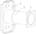
A contractile type automobile energy-absorbing beam comprises an installation support, a contractile beam and a fixed support. The contractile beam comprises a first circular tube, a second circular tube, and a closed annual connecting part, wherein the lower end of the first circular tube is fixed on the installation support, the inner diameter of the first circular tube is larger than the outer diameter of the second circular tube, the upper end of the first circular tube is connected with the lower end of the second circular tube through the closed annual connecting part to form the step-shaped contractile beam, the upper end face of the second circular tube is fixed on the fixed support, and the whole contractile type automobile energy-absorbing beam is installed at the connection portion of two ends of an automobile beam and a longitudinal beam. The contractile type automobile energy-absorbing beam has the advantages of being low in manufacture cost and simple in manufacture craft. In addition, the contractile type automobile energy-absorbing beam further has the advantages of effectively reducing instant impact rigidity, generating stable plastic deformation, fully absorbing collision energy, protecting safety of passengers and an automobile, and achieving the purpose of improving crashworthy safety of the automobile.
Description
Technical field
The utility model relates to a kind of shrinkage type automobile energy-absorbing beam.
Background technology
Automobile collision energy absorber is the critical component of automobile, occupies very important position in vehicle passive safety.The energy that produces when automobile bumps mainly is that the plastic deformation by energy absorption device absorbs.In the existing body structure, the collision energy-absorbing device of installing in the vehicle mainly comprises energy-absorbing beam etc.The energy-absorbing beam of design has following requirement, and when automobile generation low speed head-on crash, the energy-absorbing beam absorbs whole impact kinetic energies, and the impact of energy-absorbing beam can not surpass the bump License Value, in order to avoid be delivered to the parts such as front side member, causes extra destruction; When automobile generation high-speed crash, the energy-absorbing beam is answered absorbed energy as much as possible, in the collision process, and stressed even distribution, stabilization.
The day for announcing is on July 4th, 2012, and notification number is that the Chinese patent of CN202294642U discloses a kind of energy-absorption box device, and described energy-absorption box device comprises: shell and inner honeycomb core form the honeycomb hole longitudinal arrangement of honeycomb core.Its advantage is that this energy-absorption box increases aluminium honeycomb core makes the energy-absorption box stabilization, reaches the purpose of high energy-absorbing when head-on crash occurs.Its weak point is that this energy absorption device adds after the honeycomb core, and the longitudinal rigidity of energy-absorption box self is excessive.When bumping, the impact of this energy-absorption box surpasses the bump License Value easily, is directly delivered to the vitals such as front side member, and energy absorption device has just been lost its due energy-absorbing effect, so that front side member and vehicle body be damaged, and injures at last occupant's life security.
Summary of the invention
Present automotive body structure energy-absorbing beam energy-absorbing effect in collision process is undesirable in order to solve, collision process is out of shape unsettled problem, the utility model proposes a kind ofly can fully absorb the distortion of collision energy, stabilized contraction in automobile collision procedure, protect the shrinkage type automobile energy-absorbing beam of occupant and vehicle safety to greatest extent.
Shrinkage type automobile energy-absorbing beam described in the utility model, it is characterized in that: comprise mounting bracket, contraction beam and fixed support, described contraction beam comprises the first pipe, the second pipe and closed ring attaching parts, the lower end of described the first pipe is fixed on the described mounting bracket, the internal diameter of described the first pipe is greater than the external diameter of described the second pipe, and the upper end of described the first pipe is connected with the lower end of described the second pipe by the closed ring attaching parts, form step-like contraction beam, the upper end end face of described the second pipe is fixed on the described fixed support; Whole described shrinkage type automobile energy-absorbing beam is installed in the junction of vehicle beam two ends and longeron.
Further, the length ratio of described the second pipe and described the first pipe is between 1.8:1 ~ 2.2:1.
Further, the central axes of described the first pipe, described the second pipe and described closed ring attaching parts.
Perhaps, the angle of the central axis of the central axis of described the first pipe and described the second pipe is acute angle.
Further, the wall thickness of described the first pipe, described the second pipe and described closed ring attaching parts is identical.
Further, on described the second pipe some grooves are set circumferentially.
Further, the caliber of the width of described closed ring attaching parts, described the first pipe and described the second pipe and wall thickness require to determine according to vehicle parameter and vehicle safety.
The intensity of the material that the intensity of the material that described fixed support is selected is selected greater than described contraction beam.
When vehicle generation head-on crash, crossbeam passes to fixed support and contraction beam with impact, the free flop phenomenon of pipe at first occurs in contraction beam, along with the pipe upset, the second pipe turns up the most at last and forms double-deck pipe and be nested in the first pipe inner, and the conquassation that makes the energy-absorbing beam freely is turned to three layers of pipe together by conquassation from the first pipe, enters at last the densification stage, fully Folding Deformation reaches high purpose than energy-absorbing; Fixed support can make the contraction beam pipe keep cross-sectional plane complete in collision process, the pipe of contraction beam is freely overturn carry out smoothly.
The beneficial effects of the utility model are: cheap for manufacturing cost, manufacturing process is simple, can effectively reduce instantaneous impact stiffness in collision process; plastic deformation occurs to stablize; fully absorb collision energy, protection occupant and vehicle body safety reach the purpose that improves the safety of vehicle crashworthiness.
Description of drawings
Fig. 1 is constructional drawing of the present utility model (the first pipe, described the second pipe central axis angle are the acute angle state).
Fig. 2 is constructional drawing of the present utility model (the first pipe, described the second pipe central axes state).
Fig. 3 is the A-A cutaway view of Fig. 2.
Fig. 4 is the partial enlarged drawing of the closed ring attaching parts of Fig. 3.
Fig. 5 is the contraction beam of the present utility model scheme drawing (the second pipe does not insert the state in the first pipe) that freely overturns.
Fig. 6 is the contraction beam of the present utility model scheme drawing (the second pipe inserts the state in the first pipe) that freely overturns.
The specific embodiment
Further specify the utility model below in conjunction with accompanying drawing
With reference to accompanying drawing:
Shrinkage type automobile energy-absorbing beam described in the utility model, comprise mounting bracket 1, contraction beam 2 and fixed support 3, described contraction beam 2 comprises the first pipe 21, the second pipe 22 and closed ring attaching parts, the lower end of described the first pipe 21 is fixed on the described mounting bracket 1, the internal diameter of described the first pipe 21 is greater than the external diameter of described the second pipe 22, and the upper end of described the first pipe 21 is connected with the lower end of described the second pipe 22 by closed ring attaching parts 23, form step-like contraction beam 2, the upper end end face of described the second pipe 22 is fixed on the described fixed support 3; Whole described shrinkage type automobile energy-absorbing beam is installed in the junction of vehicle beam two ends and longeron.
Further, the length ratio of described the second pipe 22 and described the first pipe 21 is between 1.8:1 ~ 2.2:1.
Further, the central axes of described the first pipe 21, described the second pipe 22 and described closed ring attaching parts 23.
Perhaps, the angle of the central axis of the central axis of described the first pipe 21 and described the second pipe 22 is acute angle.
Further, the wall thickness of described the first pipe 21, described the second pipe 22 and described closed ring attaching parts 23 is identical.
Further, on described the second pipe 22 some grooves are set circumferentially.
Further, the caliber of the width of described closed ring attaching parts 23, described the first pipe 21 and described the second pipe 22 and wall thickness require to determine according to vehicle parameter and vehicle safety.
The intensity of the material that the intensity of the material that described fixed support 3 is selected is selected greater than described contraction beam 2.
When vehicle generation head-on crash, crossbeam passes to fixed support 3 and contraction beam 2 with impact, the free flop phenomenon of pipe at first occurs in contraction beam 2, along with the pipe upset, the second pipe 22 turns up the most at last and forms double-deck pipe and be nested in the first pipe 21 inside, and the conquassation that makes energy-absorbing beam 2 freely is turned to three layers of pipe together by conquassation from the first pipe 21, enters at last the densification stage, fully Folding Deformation reaches high purpose than energy-absorbing; Fixed support 3 can make contraction beam 2 keep cross-sectional plane complete in collision process, the pipe of contraction beam 2 is freely overturn carry out smoothly.
The described content of this specification sheets embodiment only is enumerating the way of realization of utility model design; protection domain of the present utility model should not be regarded as only limiting to the concrete form that embodiment states, protection domain of the present utility model also reaches the equivalent technologies means that design can be expected according to the utility model in those skilled in the art.
Claims (8)
1. shrinkage type automobile energy-absorbing beam, it is characterized in that: comprise mounting bracket, contraction beam and fixed support, described contraction beam comprises the first pipe, the second pipe and closed ring attaching parts, the lower end of described the first pipe is fixed on the described mounting bracket, the internal diameter of described the first pipe is greater than the external diameter of described the second pipe, and the upper end of described the first pipe is connected with the lower end of described the second pipe by the closed ring attaching parts, form step-like contraction beam, the upper end end face of described the second pipe is fixed on the described fixed support; Whole described shrinkage type automobile energy-absorbing beam is installed in the junction of vehicle beam two ends and longeron.
2. shrinkage type automobile energy-absorbing beam as claimed in claim 1, it is characterized in that: the length ratio of described the second pipe and described the first pipe is between 1.8:1 ~ 2.2:1.
3. shrinkage type automobile energy-absorbing beam as claimed in claim 2 is characterized in that: the central axes of described the first pipe, described the second pipe and described closed ring attaching parts.
4. shrinkage type automobile energy-absorbing beam as claimed in claim 2, it is characterized in that: the angle of the central axis of the central axis of described the first pipe and described the second pipe is acute angle.
5. shrinkage type automobile energy-absorbing beam as claimed in claim 3, it is characterized in that: the wall thickness of described the first pipe, described the second pipe and described closed ring attaching parts is identical.
6. shrinkage type automobile energy-absorbing beam as claimed in claim 5 is characterized in that: on described the second pipe some grooves are set circumferentially.
7. shrinkage type automobile energy-absorbing beam as claimed in claim 6 is characterized in that: the caliber of the width of described closed ring attaching parts, described the first pipe and described the second pipe and wall thickness require to determine according to vehicle parameter and vehicle safety.
8. shrinkage type automobile energy-absorbing beam as claimed in claim 7 is characterized in that: the intensity of the material that the intensity of the material that described fixed support is selected is selected greater than described contraction beam.
Priority Applications (1)
| Application Number | Priority Date | Filing Date | Title |
|---|---|---|---|
| CN 201220491463 CN202879409U (en) | 2012-09-25 | 2012-09-25 | Contractile type automobile energy-absorbing beam |
Applications Claiming Priority (1)
| Application Number | Priority Date | Filing Date | Title |
|---|---|---|---|
| CN 201220491463 CN202879409U (en) | 2012-09-25 | 2012-09-25 | Contractile type automobile energy-absorbing beam |
Publications (1)
| Publication Number | Publication Date |
|---|---|
| CN202879409U true CN202879409U (en) | 2013-04-17 |
Family
ID=48070867
Family Applications (1)
| Application Number | Title | Priority Date | Filing Date |
|---|---|---|---|
| CN 201220491463 Expired - Fee Related CN202879409U (en) | 2012-09-25 | 2012-09-25 | Contractile type automobile energy-absorbing beam |
Country Status (1)
| Country | Link |
|---|---|
| CN (1) | CN202879409U (en) |
Cited By (2)
| Publication number | Priority date | Publication date | Assignee | Title |
|---|---|---|---|---|
| CN102862537A (en) * | 2012-09-25 | 2013-01-09 | 浙江工业大学 | Shrinkage-type automobile energy absorption beam |
| TWI679136B (en) * | 2018-11-23 | 2019-12-11 | 財團法人金屬工業研究發展中心 | Collision buffer |
-
2012
- 2012-09-25 CN CN 201220491463 patent/CN202879409U/en not_active Expired - Fee Related
Cited By (2)
| Publication number | Priority date | Publication date | Assignee | Title |
|---|---|---|---|---|
| CN102862537A (en) * | 2012-09-25 | 2013-01-09 | 浙江工业大学 | Shrinkage-type automobile energy absorption beam |
| TWI679136B (en) * | 2018-11-23 | 2019-12-11 | 財團法人金屬工業研究發展中心 | Collision buffer |
Similar Documents
| Publication | Publication Date | Title |
|---|---|---|
| CN203255261U (en) | Automobile front wall panel reinforcing structure and automobile front wall panel assembly | |
| CA2901272C (en) | Impact absorbing element | |
| CN105102295B (en) | Rail truck collision energy absorbing and rail truck | |
| CN204249970U (en) | A kind of multistage energy-absorption type front anticollision beam of automobile | |
| CN202863357U (en) | Automobile energy absorbing cartridge | |
| WO2015092832A1 (en) | Collision energy absorption device for railway vehicle | |
| CN204821718U (en) | Car longitudinal beams , sub vehicle frame assembly and car | |
| CN104590178A (en) | Automobile energy absorption box | |
| CN110949295B (en) | Anti-collision beam assembly of passenger car | |
| CN108297939B (en) | Collision energy absorption device, front longitudinal beam, frame and automobile | |
| CN205059492U (en) | Crashproof roof beam assembly before vehicle reaches | |
| CN202879409U (en) | Contractile type automobile energy-absorbing beam | |
| CN205010335U (en) | Car roof side rail and car | |
| CN102862537A (en) | Shrinkage-type automobile energy absorption beam | |
| CN203427725U (en) | Vehicle front anti-collision beam | |
| CN103950418B (en) | Automobile carbon fiber composite material bumper | |
| CN205554105U (en) | Composite construction's car energy -absorbing box | |
| WO2017034501A1 (en) | Nested crash box as a passive safety component in vehicles | |
| AU2022424063A1 (en) | Vehicle engine cabin structure and vehicle | |
| CN203344874U (en) | Energy absorbing box and automobile anti-collision rod | |
| CN103448803B (en) | A kind of Floor rear crossbeam strengthens structure | |
| CN204309894U (en) | A kind of automobile rear longitudinal girder and automobile | |
| CN203567666U (en) | Anti-collision beam device of oil tank truck | |
| CN204567536U (en) | Front anticollision beam of automobile | |
| CN205220580U (en) | Energy -absorbing device of vehicle anticollision gear of resistance to compression cap and applied this resistance to compression cap |
Legal Events
| Date | Code | Title | Description |
|---|---|---|---|
| C14 | Grant of patent or utility model | ||
| GR01 | Patent grant | ||
| CF01 | Termination of patent right due to non-payment of annual fee |
Granted publication date: 20130417 Termination date: 20150925 |
|
| EXPY | Termination of patent right or utility model |