CN202840853U - Rotary motor maintaining device - Google Patents
Rotary motor maintaining device Download PDFInfo
- Publication number
- CN202840853U CN202840853U CN 201220554321 CN201220554321U CN202840853U CN 202840853 U CN202840853 U CN 202840853U CN 201220554321 CN201220554321 CN 201220554321 CN 201220554321 U CN201220554321 U CN 201220554321U CN 202840853 U CN202840853 U CN 202840853U
- Authority
- CN
- China
- Prior art keywords
- workbench
- motor
- support
- bracing frame
- examination
- Prior art date
- Legal status (The legal status is an assumption and is not a legal conclusion. Google has not performed a legal analysis and makes no representation as to the accuracy of the status listed.)
- Expired - Fee Related
Links
Images


Landscapes
- Manufacture Of Motors, Generators (AREA)
Abstract
The utility model relates to a motor maintaining device, in particular to a rotary motor maintaining device. The rotary motor maintaining device comprises a bench, two motor rollers distributed on the left and the right parallelly are mounted on the bench, two ends of each motor roller are rotatably connected onto two support frames, the bench is provided with elongated holes extending transversely and corresponding to the support frames, and the support frames are guided on the elongated holes through bolts in a transverse position adjustable manner. The rotary motor maintaining device is adaptable to maintenance of motors different in size and specification and high in universality, manufacturing and purchasing costs are lowered, and resources are saved.
Description
Technical field
The utility model relates to a kind of machine maintenance instrument, relates in particular to a kind of electric rotary machine apparatus for examination and repair.
Background technology
When carrying out machinery check and repair, the way of often taking is to adopt driving that motor is hung on inspection platform, then overhaul, overhaul or during to the motor winding at the shell to motor, need constantly to adjust motor position, yet when motor is larger, adjustment and rotation to motor need to use auxiliary the fulfiling assignment of driving a vehicle, therefore intensity of workers is large, inefficiency, and there is certain potential safety hazard, needs in case of necessity at least 2 people just can fulfil assignment, cause labour's waste.
For the above-mentioned situation that does not have the motor special inspection platform, publication No. is that the Chinese patent application " workbench for maintaining motor " of CN 102049768A discloses a kind of workbench for electrical machmary maintenance, comprise the support for support table, being provided with on the support can be around the workbench of self central rotation, the workbench left and right sides is equipped with two motor carrying rollers along the fore-and-aft direction extension, these two motor carrying rollers can be along self axis rotation, during use, motor to be keeped in repair is placed on the motor carrying roller on the work top.In the maintenance process, motor can be done 360 ° of rotations in the horizontal direction with workbench around its center, motor places on the motor carrying roller, therefore motor can be with the motor carrying roller around 360 ° of rotations of self axis, just the motor of can easily adjusting and overturn during maintenance, reduce intensity of workers, increase work efficiency.But the distance in this device between two motor carrying rollers is fixed, and need the workbench of plurality of specifications for the maintenance of the motor of different size specification, so this workbench versatility is poor, is unfavorable for the saving of resource.
The utility model content
The purpose of this utility model provides the good electric rotary machine apparatus for examination and repair of a kind of versatility.
For addressing the above problem, the technical solution adopted in the utility model is:
The electric rotary machine apparatus for examination and repair, comprise about being equipped with and the workbench of two motor carrying rollers of column distribution, each motor carrying roller two ends is rotationally connected with respectively on two bracing frames, described workbench offers the slotted hole corresponding with each bracing frame that extends along left and right directions, and described each bracing frame is assemblied on the slotted hole by the adjustable guiding in position, the bolt left and right sides.
Described workbench below is provided with support, is provided with between described support and the workbench to make between described workbench and the described support in relative rotation whirligig.
Described whirligig is to be threaded onto the in relative rotation main shaft that makes between workbench and the support in the through hole of offering on workbench and the support by thrust bearing between workbench and the support.
Described motor carrying roller has central shaft and can rotate around its central shaft, and described central shaft two ends are welded on the corresponding bracing frame.
The beneficial effects of the utility model are: a kind of electric rotary machine apparatus for examination and repair, the workbench left and right sides is set up in parallel two motor carrying rollers, the Awaiting Overhaul motor can be positioned on this motor carrying roller, these two motor carrying rollers are rotationally connected with on the bracing frame, bracing frame can be adjusted along about the slotted hole of offering on the workbench according to the dimensions of motor to be detected, thereby make the size of the distance adaptation motor to be detected between the motor carrying roller that is attached thereto, the stability of motor when improving maintenance.In the utility model between the two motor carrying rollers distance adjustable, be applicable to the motor of different size specification, versatility is good, is conducive to the saving of resource.
Further, be provided with whirligig between workbench and the support, convenient recoil to the motor winding is increased work efficiency.
Further, install a main shaft by thrust bearing and realize relatively rotating between workbench and the support in the workbench through hole corresponding with support, bearing capacity is high.
Further, the motor carrying roller can around self central shaft rotation, be convenient to the maintenance to motor housing.
Description of drawings
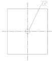
Fig. 1 is the assembly structure schematic diagram of the utility model embodiment;
Fig. 2 is the A-A cutaway view of Fig. 1;
Fig. 3 is the front view of workbench 1 among Fig. 1;
Fig. 4 is the left view of Fig. 3;
Fig. 5 is the front view of Fig. 1 medium-height trestle supporting surface 2;
Fig. 6 is the left view of Fig. 5;
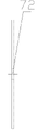
Fig. 7 is the front view of main shaft 9 among Fig. 1;
Fig. 8 is the left view of Fig. 7;
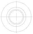
Fig. 9 is the front view of cutting ferrule 100 on the upper bearing (metal) among Fig. 2;
Figure 10 is the right view of Fig. 9;
Figure 11 is the front view of cutting ferrule 103 under the lower bearing among Fig. 2;
Figure 12 is the left view of Figure 11;
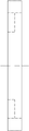
Figure 13 is the front view of bracing frame among Fig. 1;
Figure 14 is the left view of Figure 13;
Figure 15 is the vertical view of Figure 13.
Embodiment
Embodiment of the present utility model is elaborated to present embodiment below in conjunction with accompanying drawing shown in Fig. 1~15:
A kind of electric rotary machine apparatus for examination and repair, comprise support, support adopts the rectangle steel plate as supporting surface 2, the place, four angles of supporting surface 2 lower surfaces is provided with respectively a supporting leg 3, offer be used to the lower through-hole 72 that installs main shaft in the middle of the supporting surface 2, workbench 1 is a rectangle steel plate, workbench about 1 is distributed with left motor carrying roller 51 and right motor carrying roller 52 side by side, two motor carrying rollers have respectively central shaft separately, two motor carrying rollers respectively can be around central shaft rotation separately, the central shaft of two motor carrying rollers all stretches out from motor carrying roller two ends and is welded and fixed with corresponding bracing frame, for adapting to the motor of different size, on workbench, offer two pairs of slotted holes 4 along the left and right directions symmetry, described slotted hole 4 extends along left and right directions, described each bracing frame all adopts the adjustable guiding in the bolt left and right sides to be assemblied in the corresponding slotted hole 4, the bracing frame bottom surface is the rectangle steel plate that offers be used to the circular hole 8 that installs respective bolt, be fixed with the steel plate of a trapezium structure along its one side vertical welding in its bottom surface, support frame as described above is four, comprise right anterior branch support 61, right back bracing frame 62, left front bracing frame 63 and left back bracing frame 64, the central shaft front and back end of described left motor carrying roller 52 is weldingly fixed on respectively on left front bracing frame 63 and the left back bracing frame 64, the central shaft front and back end of described right motor carrying roller 51 is weldingly fixed on respectively on right anterior branch support 61 and the right back bracing frame 62, position corresponding with the lower through-hole 72 of supporting surface 2 in the middle of the workbench 1 offers upper through hole 71, lower surface around the upper through hole of workbench 1 is welded with cutting ferrule 100 on the upper bearing (metal), up-thrust bearing is installed in the trepanning that cutting ferrule 100 is offered on upper bearing (metal), adopt under the upper bearing (metal) identical with cutting ferrule 100 structures on the upper bearing (metal) on cutting ferrule 101 and the upper bearing (metal) cutting ferrule 100 to be interlocked with fixing up-thrust bearing, so cutting ferrule 100 on the upper bearing (metal), cutting ferrule 101 is located between the supporting surface 2 of workbench 1 and support under up-thrust bearing and the upper bearing (metal), the main shaft 9 of multidiameter shape penetrates along upper through hole 71 from the upper surface of workbench 1, pass successively workbench 1, cutting ferrule 100 on the upper bearing (metal), up-thrust bearing, cutting ferrule 101 under the upper bearing (metal), and the lower through-hole 72 of offering from the supporting surface 2 of support passes, to be sleeved on cutting ferrule 102 on the lower bearing of cutting ferrule same structure on the upper bearing (metal) traversing through end of main shaft 9, lower thrust-bearing is installed in the trepanning that cutting ferrule 102 is offered on lower bearing, cutting ferrule under the lower bearing 103 is sleeved on the main shaft 9 and with lower bearing on cutting ferrule 102 fasten, cutting ferrule 103 belows adopt nut 12 to screw in and upwards compress that cutting ferrule 103 is fixed under the lower bearing under the lower bearing.
During use, according to the size of Awaiting Overhaul motor with bracing frame along the slotted hole guiding movement to the appropriate location and adopt bolt to be fixed, because left motor carrying roller 52 and right motor carrying roller 51 are weldingly fixed on the corresponding bracing frame, therefore two motor carrying roller positions are fixed, the Awaiting Overhaul motor is placed on two motor carrying rollers top, when maintenance, rotary table 1, workbench 1 relative support under being rotatably assorted of main shaft and bearing can be finished 360 ° rotation, consisting of between Awaiting Overhaul motor excircle and left motor carrying roller 52 and the right motor carrying roller 51 rolls cooperates, can be easily do 360 ° rotation around himself axis, therefore when the maintenance motor, only need a staff just can easily finish the maintenance of motor housing and the work of motor winding rewinding, reduced labour intensity, improved operating efficiency, convenient, fast, safety.
Being provided with support below the workbench and counterrotating whirligig being set, also can not use support in other embodiments in the present embodiment between support and workbench, and adopt driving mechanism commonly used directly to drive worktable rotary.
The whirligig that adopts in the present embodiment is to be threaded onto being rotatably assorted of axle in workbench and the support and bearing, also can adopt such as the method in the background technology in other embodiments, at workbench rotating disk is installed, is finished in the horizontal direction 360 ° rotation in order to realize motor to be detected.
Claims (4)
1. electric rotary machine apparatus for examination and repair, comprise about being equipped with and the workbench of two motor carrying rollers of column distribution, it is characterized in that: each motor carrying roller two ends is rotationally connected with respectively on two bracing frames, described workbench offers the slotted hole corresponding with each bracing frame that extends along left and right directions, and described each bracing frame is assemblied on the slotted hole by the adjustable guiding in position, the bolt left and right sides.
2. electric rotary machine apparatus for examination and repair according to claim 1 is characterized in that: described workbench below is provided with support, is provided with between described support and the workbench to make between described workbench and the described support in relative rotation whirligig.
3. electric rotary machine apparatus for examination and repair according to claim 2 is characterized in that: described whirligig is to be threaded onto the in relative rotation main shaft that makes between workbench and the support in the through hole of offering on workbench and the support by thrust bearing between workbench and the support.
4. the described electric rotary machine apparatus for examination and repair of any one according to claim 1~3 is characterized in that: described motor carrying roller has central shaft and can rotate around its central shaft, and described central shaft two ends are welded on the corresponding bracing frame.
Priority Applications (1)
| Application Number | Priority Date | Filing Date | Title |
|---|---|---|---|
| CN 201220554321 CN202840853U (en) | 2012-10-26 | 2012-10-26 | Rotary motor maintaining device |
Applications Claiming Priority (1)
| Application Number | Priority Date | Filing Date | Title |
|---|---|---|---|
| CN 201220554321 CN202840853U (en) | 2012-10-26 | 2012-10-26 | Rotary motor maintaining device |
Publications (1)
| Publication Number | Publication Date |
|---|---|
| CN202840853U true CN202840853U (en) | 2013-03-27 |
Family
ID=47952455
Family Applications (1)
| Application Number | Title | Priority Date | Filing Date |
|---|---|---|---|
| CN 201220554321 Expired - Fee Related CN202840853U (en) | 2012-10-26 | 2012-10-26 | Rotary motor maintaining device |
Country Status (1)
| Country | Link |
|---|---|
| CN (1) | CN202840853U (en) |
Cited By (2)
| Publication number | Priority date | Publication date | Assignee | Title |
|---|---|---|---|---|
| CN103337935A (en) * | 2013-06-21 | 2013-10-02 | 苏州市圣玛特电机设备制造有限公司 | Insulation paper inserting machine for motor stator |
| CN105449942A (en) * | 2015-12-31 | 2016-03-30 | 上海振华重工集团(南通)传动机械有限公司 | Rotatable motor test tool |
-
2012
- 2012-10-26 CN CN 201220554321 patent/CN202840853U/en not_active Expired - Fee Related
Cited By (3)
| Publication number | Priority date | Publication date | Assignee | Title |
|---|---|---|---|---|
| CN103337935A (en) * | 2013-06-21 | 2013-10-02 | 苏州市圣玛特电机设备制造有限公司 | Insulation paper inserting machine for motor stator |
| CN105449942A (en) * | 2015-12-31 | 2016-03-30 | 上海振华重工集团(南通)传动机械有限公司 | Rotatable motor test tool |
| CN105449942B (en) * | 2015-12-31 | 2017-11-28 | 上海振华重工集团(南通)传动机械有限公司 | A kind of rotary type motor running-in fixture |
Similar Documents
| Publication | Publication Date | Title |
|---|---|---|
| CN202878283U (en) | Rotating tool frame | |
| CN201841108U (en) | Rotary workbench | |
| CN206860378U (en) | It is a kind of to embrace tower apparatus for wind-power tower maintenance | |
| CN201559030U (en) | Mounting-welding clamp workbench rotating device for automotive body | |
| CN202840853U (en) | Rotary motor maintaining device | |
| CN214977285U (en) | Cold roll forming equipment roll-in feeding guiding mechanism | |
| CN205043708U (en) | Motor overhauls specialized tool | |
| CN211540844U (en) | Clamping device for surface grinding machine | |
| CN211195339U (en) | Stamp device with fine setting structure | |
| CN104492879A (en) | Rolling machine with rollers adjustable independently | |
| CN206689671U (en) | A kind of adjustable jig | |
| CN201998081U (en) | Workpiece rotating device | |
| CN207139180U (en) | One kind welding upset platform | |
| CN216576288U (en) | Flange and tower section assembly special machine for wind power tower drum manufacturing | |
| CN206967029U (en) | A kind of portable mounting platform | |
| CN106882719B (en) | Low clearance electric hoist with endless chain | |
| CN210549826U (en) | Loading frame of plate cutting machine | |
| CN210943552U (en) | Feeding equipment is used in processing of ashtray bracket for car | |
| CN213579232U (en) | Z-axis transmission balance adjusting device of three-coordinate measuring machine | |
| CN111422682A (en) | Electric power construction project management device | |
| CN211338703U (en) | Slotting elevator | |
| CN207121123U (en) | A kind of full-automatic lifting material conveying platform | |
| CN218335458U (en) | Motor stator assembly convenient to transport | |
| CN214184670U (en) | Winding device for producing steel wire of automobile seat framework | |
| CN215699690U (en) | Workstation is used in machining convenient to remove |
Legal Events
| Date | Code | Title | Description |
|---|---|---|---|
| C14 | Grant of patent or utility model | ||
| GR01 | Patent grant | ||
| C17 | Cessation of patent right | ||
| CF01 | Termination of patent right due to non-payment of annual fee |
Granted publication date: 20130327 Termination date: 20131026 |