CN202834639U - Fixed type wall hanging support - Google Patents
Fixed type wall hanging support Download PDFInfo
- Publication number
- CN202834639U CN202834639U CN 201220185206 CN201220185206U CN202834639U CN 202834639 U CN202834639 U CN 202834639U CN 201220185206 CN201220185206 CN 201220185206 CN 201220185206 U CN201220185206 U CN 201220185206U CN 202834639 U CN202834639 U CN 202834639U
- Authority
- CN
- China
- Prior art keywords
- upper arm
- automatic locking
- wall hanging
- hanging
- column
- Prior art date
- Legal status (The legal status is an assumption and is not a legal conclusion. Google has not performed a legal analysis and makes no representation as to the accuracy of the status listed.)
- Expired - Fee Related
Links
Images


Abstract
The utility model aims to resolve the problems that an existing wall hanging support is time-consuming and labor-consuming to install, and inconvenience is brought to users and operators, and provides a fixed type wall hanging support which is convenient to assemble and disassemble. The wall hanging support comprises a wall surface board and at least two supporting arm parts used for installation of to-be-installed products, wherein the wall surface board is fixed on a wall surface, each supporting arm comprises a hanging arm and an automatic locking mechanism arranged on the hanging arm, the hanging arms are arranged on the wall surface board through hanging lugs and the automatic locking mechanism, and each hanging lug is arranged at one end of each hanging arm and is hung on the wall surface board in a buckled mode. According to the fixed type wall hanging support, the to-be-installed products are directly fixed on the hanging arms which are hung on the wall surface board through the hanging lugs, and installation of the whole wall hanging support is completed through automatic locking of the locking mechanism. When the products need disassembling, the locking mechanism is unlocked, the products are disassembled from the hanging arms then, the operation method that the products are disassembled separately after unlocking is achieved, simultaneous unlocking and disassembling are not needed, time is saved, labor is saved, and using convenience is achieved.
Description
Technical field
The utility model relates to the wall hanging mechanism technical field, specifically, relates to a kind of fixed wall hanging rack.
Background technique
Along with the raising of people to interior space utilization ratio, wall hanging mechanism begins to popularize, and especially is accompanied by the popularization of LCD product, and such as LCD TVs, liquid crystal display etc., the research and development of wall hanging mechanism and the paces of production are also constantly accelerated.The effect of wall hanging mechanism mainly is that LCD product is fixedly installed on the body of wall, and need not other placements or the supporting LCD product device, saved the space, improved interior space utilization ratio, so that the installation of LCD product no longer is subjected to the restriction of Environmental Conditions, as long as there is the position of body of wall or wallboard all LCD product can be installed.
The wall hanging of prior art props up hanger and generally comprises shingle nail, and at shingle nail arm part is set, and LCD product is connected with main hanger by arm part, and during installation, first shingle nail is fixed on the body of wall, and LCD product is installed on the shingle nail by arm part.Simultaneously, also can locking mechanism be set at above-mentioned wall hanging rack, after soon LCD product installed, locking mechanism automatically locked, when needs dismounting LCD product, first will be to the locking mechanism release, in the process of release, need simultaneously operation to pull down LCD product, an operator is difficult to finish simultaneously above-mentioned two actions, detaching products is wasted time and energy, and makes troubles for user and operator.
The model utility content
The utility model is wasted time and energy in order to solve existing wall hanging rack installation and removal, and the inconvenience of bringing for user and operator provides a kind of fixed wall hanging rack that can mount and dismount easily.
The technical problem of the required solution of the utility model can be achieved through the following technical solutions:
A kind of fixed wall hanging rack, comprise shingle nail and at least two arm parts that are used for installing product to be installed of being fixed on the metope, it is characterized in that: described arm part comprises upper arm and is arranged on automatic locking mechanism on the upper arm, and upper arm is installed on the shingle nail by hangers and the automatic locking mechanism that is arranged on upper arm one end button and hangs on the shingle nail.
In the utility model, described automatic locking mechanism comprises release buckle, pedestal and automatic locking, in the described pedestal stage clip is housed, and release buckle, pedestal and automatic locking are installed on the upper arm successively.
Described automatic locking bottom is provided with stay cord, so that automatic locking mechanism is carried out release.
In the utility model, the free end of described upper arm is provided with original state towards a side of wall and is close to upper arm, the column that can rotate along vertical plane, and the rotating shaft of described column is arranged on the upper arm free end towards a side of wall.
Described upper arm free end is provided with the fixing described column of original state towards a side of wall, discharge the column buckle of column behind the pressurized, so that when upper arm tilts, when withstanding wall, the column buckle automatically discharges column, can be easily the wire harness at the product to be installed back side be managed.
Rotating shaft place of described column is provided with spacing preiection, and the maximum rotation angle of described column is 90 degree.
In the utility model, for the shingle nail that makes is horizontally fixed on the metope, described shingle nail is provided with spirit bubble.
Fixed wall hanging rack of the present utility model, product to be installed is directly fixed on the upper arm, and upper arm is buckled by hangers and is hung on the shingle nail, and locking mechanism automatically locks and finishes the installation of whole wall hanging rack, when needing the dismounting product, under the upper arm dismounting, realized first release first to the locking mechanism release, and then with product, pull down separately again the mode of operation of product, need not synchronizing unlocking and dismounting, time saving and energy saving, very easy to use.
Description of drawings
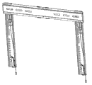
Fig. 1 is the structural representation of the utility model shingle nail and arm part;
Fig. 2 is the structural representation of the utility model arm part;
Fig. 3 is the explosive view of the utility model arm part;
Fig. 4 is the utility model automatic locking mechanism locking state schematic diagram;
Fig. 5 is the utility model automatic locking mechanism released state schematic diagram;
Fig. 6 is the structural representation of the utility model column releasing state.
Embodiment
In order to make technological means of the present utility model, creation characteristic, to reach purpose and effect is easy to understand, below in conjunction with concrete diagram, further set forth the utility model.
It is a kind of easy to use that purport of the present utility model is to provide, during LCD product on needing the removal wall hanging bracket, can at first carry out release to locking mechanism, dismantle again the wall hanging rack of lower LCD product, even so that an operator also can dismantle LCD product, improve the installation and removal efficient of LCD product, better experience is provided for user and operator.
Referring to Fig. 1; fixed wall hanging rack of the present utility model comprises a shingle nail 1; shingle nail 1 is the basis of whole fixed wall hanging rack; it is fixed on the wall by the fixing mode of screw usually; simultaneously, for so that shingle nail 1 keeps level after being fixed on the wall, can spirit bubble 11 be set at shingle nail 1; for fixing and level of protection bubble 11, can be correspondingly at spirit bubble 11 arranged outside spirit bubble cover plates 12.
Arm part 2 is installed on the shingle nail 1 (among Fig. 1 for not installment state), 2 of arm parts are used for installing product to be installed (for example LCD product), arm part 2 is made of upper arm 210 and the automatic locking mechanism (signal among Fig. 1) that is arranged on the upper arm 210, is provided with the through hole of the circular hole, elongated hole or other shapes that match with product mounting assembly to be installed on the upper arm 210.Be understandable that, for so that product to be installed can stably be installed on the wall hanging rack, arm part 2 should be at least two.During large the or out-of-shape of, volume heavier when product to be installed, also can adopt the arm part 2 more than three or three.In the present embodiment, be provided with two arm parts 2 with wall hanging rack and carry out exemplary illustration, this is not limitation of the utility model.
Referring to Fig. 2 and Fig. 3, arm part 2 is core components of the present utility model, arm part 2 is made of upper arm 210 and the automatic locking mechanism 220 that is arranged on the upper arm 210 as previously mentioned, one end of wall built-up 210 is provided with hangers 211, hangers 211 buckles on shingle nail 1, is installed on the shingle nail 1 by automatic locking mechanism 220 again.
For the ease of automatic locking mechanism 220 is installed, adopted elder generation in upper arm 210 mounting hole 212 to be set in the present embodiment, then the mode of cover plate 221 is set in mounting hole 212, automatic locking mechanism 220 passes through cover plate 221 integral installations on upper arm 210, because cover plate 221 one sides are towards outer wall, for consideration attractive in appearance, can decorative pattern be set at cover plate 221.
Referring to Fig. 4, when arm part 2 is installed on the shingle nail 1, at first the hangers 211 on the upper arm 210 is buckled in the top edge of shingle nail 1, firmly push the position of automatic locking mechanism 220 on the upper arm 210, stage clip 225 resiliences in the pedestal 223, automatic locking 224 arrives shingle nail 1 lower limb towards a side of wall, and the projection of automatic locking 224 upper ends will withhold shingle nail 1 lower limb, and whole arm part 2 namely stably is installed on the shingle nail 1.
Referring to Fig. 5, when the needs release, pulling automatic locking 224, automatic locking moves to unlocking direction, release buckle 222 also moves to unlocking direction simultaneously, until release buckle 222 arrives the lower limb of shingle nail 1, even unclamp automatic locking 224, automatic locking 224 can self-resetting yet, and arm part 2 can take off from shingle nail 1.For the ease of unlocking operation, can stay cord 3 be set in the bottom of automatic locking 224, use like this stay cord 3 can finish release.
Again referring to Fig. 3, for the consideration that arm part 2 is installed to shingle nail 1 rear stability and is convenient to manage to the product wire harness is installed, in the utility model, can towards a side of wall column 227 be set at the free end of upper arm 210, the original state of column 227 before arm part 2 is not installed is close to upper arm 210, column 227 1 ends arrange rotating shaft, the rotating shaft of column 227 is arranged on upper arm 210 free ends equally towards a side of wall, after arm part 2 is installed on the shingle nail 1, can rotate column 227 along vertical plane, column 227 withstands the effect that wall plays support.Be provided with column buckle 228 at upper arm 210 free ends towards a side of wall, like this, under original state, column 227 is undertaken spacing by column buckle 228, avoided owing to the reason such as mobile so that column 227 leaves initial position.
Under this mode of execution, column 227 adopts the less rotating shaft of damping, when upper arm 210 tilts, when withstanding wall, column buckle 228 will automatically discharge column 227, simplified operating procedure, after column 227 upset is good, can be easily the wire harness at the product to be installed back side have been managed.
Fixed wall hanging rack of the present utility model is fixed on shingle nail 1 on the body of wall by swell fixture first when operation, and shingle nail 1 whether check by spirit bubble 11 by level, if but out-of-level repetitive operation; Then LCD product is directly fixed on the upper arm 210, if the upper arm 210 of need using be a plurality of then be fixed respectively, the hangers 211 of upper arm buckle and is hung on the shingle nail 1 afterwards automatic locking mechanism 220 and lock and finish installation; When needing the dismounting LCD product, first to automatic locking mechanism 220 releases, then LCD product together dismantle time with arm part 2, again LCD product is pulled down from upper arm 210 at last and got final product, need not synchronizing unlocking and dismounting, time saving and energy saving, very easy to use.
Below only be described with regard to the utility model preferred embodiment, but can not be interpreted as it is limitations on claims.The utility model not only is confined to above embodiment, and its concrete structure allows to change.In a word, all various variations of doing in the protection domain of the utility model independent claims are all in protection domain of the present utility model.
Claims (8)
1. fixed wall hanging rack, comprise shingle nail and at least two arm parts that are used for installing product to be installed of being fixed on the metope, it is characterized in that: described arm part comprises upper arm and is arranged on automatic locking mechanism on the upper arm, and upper arm is installed on the shingle nail by hangers and the automatic locking mechanism that is arranged on upper arm one end button and hangs on the shingle nail.
2. fixed wall hanging rack according to claim 1 is characterized in that: described automatic locking mechanism, comprise release buckle, pedestal and automatic locking, and in the described pedestal stage clip is housed, release buckle, pedestal and automatic locking are installed on the upper arm successively.
3. fixed wall hanging rack according to claim 2, it is characterized in that: described automatic locking bottom is provided with stay cord.
4. fixed wall hanging rack according to claim 1 and 2, it is characterized in that: the free end of described upper arm is provided with original state towards a side of wall and is close to upper arm, the column that can rotate along vertical plane, the rotating shaft of described column is arranged on the upper arm free end towards a side of wall.
5. fixed wall hanging rack according to claim 4 is characterized in that: described upper arm free end is provided with the fixing described column of original state towards a side of wall, discharges the column buckle of column behind the pressurized.
6. fixed wall hanging rack according to claim 4, it is characterized in that: rotating shaft place of described column is provided with spacing preiection, and the maximum rotation angle of described column is 90 degree.
7. fixed wall hanging rack according to claim 5, it is characterized in that: rotating shaft place of described column is provided with spacing preiection, and the maximum rotation angle of described column is 90 degree.
8. fixed wall hanging rack according to claim 1 and 2, it is characterized in that: described shingle nail is provided with spirit bubble.
Priority Applications (1)
| Application Number | Priority Date | Filing Date | Title |
|---|---|---|---|
| CN 201220185206 CN202834639U (en) | 2012-04-27 | 2012-04-27 | Fixed type wall hanging support |
Applications Claiming Priority (1)
| Application Number | Priority Date | Filing Date | Title |
|---|---|---|---|
| CN 201220185206 CN202834639U (en) | 2012-04-27 | 2012-04-27 | Fixed type wall hanging support |
Publications (1)
| Publication Number | Publication Date |
|---|---|
| CN202834639U true CN202834639U (en) | 2013-03-27 |
Family
ID=47946344
Family Applications (1)
| Application Number | Title | Priority Date | Filing Date |
|---|---|---|---|
| CN 201220185206 Expired - Fee Related CN202834639U (en) | 2012-04-27 | 2012-04-27 | Fixed type wall hanging support |
Country Status (1)
| Country | Link |
|---|---|
| CN (1) | CN202834639U (en) |
Cited By (2)
| Publication number | Priority date | Publication date | Assignee | Title |
|---|---|---|---|---|
| CN103899894A (en) * | 2014-03-27 | 2014-07-02 | 宁波乐歌视讯科技股份有限公司 | Flat-panel television set supporting device |
| CN113983307A (en) * | 2021-12-02 | 2022-01-28 | 广东天波信息技术股份有限公司 | Fixed stores pylon and face identification equipment |
-
2012
- 2012-04-27 CN CN 201220185206 patent/CN202834639U/en not_active Expired - Fee Related
Cited By (4)
| Publication number | Priority date | Publication date | Assignee | Title |
|---|---|---|---|---|
| CN103899894A (en) * | 2014-03-27 | 2014-07-02 | 宁波乐歌视讯科技股份有限公司 | Flat-panel television set supporting device |
| CN103899894B (en) * | 2014-03-27 | 2016-04-20 | 宁波乐歌视讯科技股份有限公司 | Panel TV set bearing device |
| CN113983307A (en) * | 2021-12-02 | 2022-01-28 | 广东天波信息技术股份有限公司 | Fixed stores pylon and face identification equipment |
| CN113983307B (en) * | 2021-12-02 | 2023-12-26 | 广东天波信息技术股份有限公司 | Fixed stores pylon and face identification equipment |
Similar Documents
| Publication | Publication Date | Title |
|---|---|---|
| CN202834638U (en) | Adjustable wall hanging support | |
| CN202834639U (en) | Fixed type wall hanging support | |
| CN201723951U (en) | Integrated wall-mounted bracket | |
| CN203948899U (en) | Curved surface television wall hanging | |
| CN208267017U (en) | A kind of platform basin bracket of removable installation | |
| CN204216515U (en) | The mounting structure of distribution engineering cable testing bridge | |
| CN207471081U (en) | free splicing display hanger | |
| CN202469421U (en) | Adjustable wall-mounted rack | |
| CN201772226U (en) | Hanging board for mounting panel TV set | |
| CN210369520U (en) | Pendant convenient to ceiling installation on world wall | |
| CN201462356U (en) | Wall hanging bracket of flat panel television | |
| CN202082571U (en) | Embedded display screen mounting seat | |
| CN210395801U (en) | Aluminum ceiling convenient to dismouting | |
| CN202647130U (en) | Separating television bracket | |
| CN201088435Y (en) | Wall hanging installation structure | |
| CN202001801U (en) | TV hanger | |
| CN207627133U (en) | A kind of baking oven stove control panel mounting structure | |
| CN201422820Y (en) | Hand drier mounting plate and hand drier bottom plate | |
| CN203701379U (en) | Unit type metal plate curtain wall | |
| CN219365564U (en) | Combined type unit house for exhibition | |
| CN212201779U (en) | Novel door plate structure of mobile toilet | |
| CN202091748U (en) | Rope mount mechanism for electric appliances | |
| CN216530322U (en) | High-strength fireproof bridge | |
| JP2000216553A (en) | Stand for large-screen thin display device | |
| CN216042098U (en) | Indoor suspended ceiling |
Legal Events
| Date | Code | Title | Description |
|---|---|---|---|
| C14 | Grant of patent or utility model | ||
| GR01 | Patent grant | ||
| C17 | Cessation of patent right | ||
| CF01 | Termination of patent right due to non-payment of annual fee |
Granted publication date: 20130327 Termination date: 20140427 |