CN202827157U - Power source tool for concrete mixer truck - Google Patents
Power source tool for concrete mixer truck Download PDFInfo
- Publication number
- CN202827157U CN202827157U CN 201220525530 CN201220525530U CN202827157U CN 202827157 U CN202827157 U CN 202827157U CN 201220525530 CN201220525530 CN 201220525530 CN 201220525530 U CN201220525530 U CN 201220525530U CN 202827157 U CN202827157 U CN 202827157U
- Authority
- CN
- China
- Prior art keywords
- motor
- support
- fixed mount
- counter flange
- locating support
- Prior art date
- Legal status (The legal status is an assumption and is not a legal conclusion. Google has not performed a legal analysis and makes no representation as to the accuracy of the status listed.)
- Expired - Fee Related
Links
Images


Abstract
The utility model discloses a power source tool for a concrete mixer truck. The power source tool for the concrete mixer truck comprises a motor, a motor seat, an electric cabinet and a transmission system. The motor seat is composed of an upper support, a lower support, a location support and a fixed support. The bottom of one side of the upper support is connected with the lower support through a pin roll in a hinged mode, the other side of the upper support is connected with the lower support through the location support and the fixed support, the motor is installed on the top face of the upper support which is arranged on the motor seat, a motor output shaft is connected with the transmission system, and the electric cabinet is installed in one side of the motor and is electrically connected with the motor. The power source tool for the concrete mixer truck comprises the motor, the motor seat, the electric cabinet and the transmission system and has the advantages of being simple in structure, low in cost and capable of replacing a concrete mixer truck chassis to drive a pot body to rotate in a production process, greatly reduces capital occupation and improves production efficiency.
Description
Technical field
The utility model relates to a kind of mixermobile, particularly relates to a kind of propulsion source frock of mixermobile.
Background technology
As shown in Figure 1, the processes such as the assembling of dress, debugging, application on the Mixer Truck 10 need to rotate tank body 20 and just can carry out.The power of tank body 20 is provided by chassis 30, because chassis 30 procurement payments account for integral vehicle cost approximately 70%, the occupation of capital is too high, if the hand rotation tank body, production efficiency is very low, and staff labor intensity is large.
The utility model content
The purpose of this utility model is to provide a kind of propulsion source frock of simple in structure, cheap mixermobile.
For achieving the above object, technical solution of the present utility model is:
The utility model is a kind of propulsion source frock of mixermobile, and it comprises motor, motor cabinet, electrical control cubicles, driving system; Described motor cabinet is comprised of upper bracket, lower bracket, locating support, fixed mount; One side bottom of described upper bracket is hinged by bearing pin and lower bracket, and the opposite side bottom of upper bracket is provided with to the certain position of downward-extension support, longitudinally offers a plurality of knock holees on this locating support; On the lower bracket end face relative with locating support, extend upward a fixed mount, be provided with fixed orifice at this fixed mount, locating support and fixed mount overlapping and by being arranged on the locating support locating dowel pin of fixed orifice is fixed together on the knock hole and fixed mount; Described motor is installed in the upper bracket end face of motor cabinet, and motor output shaft is connected with driving system; Described electrical control cubicles is installed in motor one side and is electrically connected motor.
Described driving system is comprised of interior counter flange, flat key, transmission shaft, outer counter flange; Described motor output shaft is connected with interior counter flange by flat key, and the two ends of transmission shaft connect respectively interior counter flange and outer counter flange.
After adopting such scheme, because the utility model mainly is comprised of parts such as motor, motor cabinet, electrical control cubicles, driving systems, and is simple in structure, cheap, can replaces in process of production the mixer lorry chassis to drive tank body and rotate, greatly reduce the occupation of capital, improved production efficiency.By regulating on the locating support the different positions that wear of fixed orifice on the knock hole and fixed mount, can regulate the gradient of motor cabinet upper bracket, in order to cooperate the Mixer Truck of differing heights, applicable vehicle is many.
Below in conjunction with the drawings and specific embodiments the utility model is further described.
Description of drawings
Fig. 1 is the mixermobile working state figure;
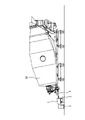
Fig. 2 is front elevation of the present utility model;
Fig. 3 is birds-eye view of the present utility model;
Fig. 4 is the schematic diagram of the utility model motor cabinet;
Fig. 5 is that the utility model uses constitution diagram.
The specific embodiment
As shown in Figure 2, the utility model is a kind of propulsion source frock of mixermobile, and it comprises motor 1, motor cabinet 2, electrical control cubicles 3, driving system 4.
As shown in Figure 4, described motor cabinet 2 is comprised of upper bracket 21, lower bracket 22, locating support 23, fixed mount 24.One side bottom of described upper bracket 21 is hinged by bearing pin 25 and lower bracket 22, and the opposite side bottom of upper bracket 21 is provided with to the certain position of downward-extension support 23, longitudinally offers a plurality of knock holees 231 on this locating support 23; On lower bracket 22 end faces relative with locating support 23, extend upward a fixed mount 24, be provided with fixed orifice 241 at this fixed mount 24, locating support 23 and fixed mount 24 overlapping and by being arranged on the locating support 23 locating dowel pin 26 of fixed orifice 241 is fixed together on the knock hole 231 and fixed mount 24.
As shown in Figure 3, described driving system 4 is comprised of interior counter flange 41, flat key 42, transmission shaft 43, outer counter flange 44.Described motor 1 output shaft 11 is connected with interior counter flange 41 by flat key 42, and the two ends of transmission shaft 43 connect respectively interior counter flange 41 and outer counter flange 44.
Such as Fig. 2, shown in Figure 4, described motor 1 is installed in upper bracket 21 end faces of motor cabinet 2.Described electrical control cubicles 3 is installed in motor 1 one sides and is electrically connected motor 1.
As shown in Figure 5, the utility model motor 1 drives tank body 20 by driving system 4 and rotates, for tank body 20 provides power.
During use, locating dowel pin 26 can be inserted the different knock holees 231 on the locating supports 23, thereby the gradient of regulating electric machine seat 2 upper brackets 21 needs of differing heights Mixer Truck have been satisfied.
The above, it only is the utility model preferred embodiment, the location hole count of locating support can be decided according to needs, therefore can not limit the scope that the utility model is implemented with this, the equivalence of namely doing according to the utility model claim and description changes and modifies, and all should still belong in the scope that the utility model patent contains.
Claims (2)
1. the propulsion source frock of a mixermobile, it is characterized in that: it comprises motor, motor cabinet, electrical control cubicles, driving system; Described motor cabinet is comprised of upper bracket, lower bracket, locating support, fixed mount; One side bottom of described upper bracket is hinged by bearing pin and lower bracket, and the opposite side bottom of upper bracket is provided with to the certain position of downward-extension support, longitudinally offers a plurality of knock holees on this locating support; On the lower bracket end face relative with locating support, extend upward a fixed mount, be provided with fixed orifice at this fixed mount, locating support and fixed mount overlapping and by being arranged on the locating support locating dowel pin of fixed orifice is fixed together on the knock hole and fixed mount; Described motor is installed in the upper bracket end face of motor cabinet, and motor output shaft is connected with driving system; Described electrical control cubicles is installed in motor one side and is electrically connected motor.
2. the propulsion source frock of mixermobile according to claim 1, it is characterized in that: described driving system is comprised of interior counter flange, flat key, transmission shaft, outer counter flange; Described motor output shaft is connected with interior counter flange by flat key, and the two ends of transmission shaft connect respectively interior counter flange and outer counter flange.
Priority Applications (1)
| Application Number | Priority Date | Filing Date | Title |
|---|---|---|---|
| CN 201220525530 CN202827157U (en) | 2012-10-15 | 2012-10-15 | Power source tool for concrete mixer truck |
Applications Claiming Priority (1)
| Application Number | Priority Date | Filing Date | Title |
|---|---|---|---|
| CN 201220525530 CN202827157U (en) | 2012-10-15 | 2012-10-15 | Power source tool for concrete mixer truck |
Publications (1)
| Publication Number | Publication Date |
|---|---|
| CN202827157U true CN202827157U (en) | 2013-03-27 |
Family
ID=47938929
Family Applications (1)
| Application Number | Title | Priority Date | Filing Date |
|---|---|---|---|
| CN 201220525530 Expired - Fee Related CN202827157U (en) | 2012-10-15 | 2012-10-15 | Power source tool for concrete mixer truck |
Country Status (1)
| Country | Link |
|---|---|
| CN (1) | CN202827157U (en) |
-
2012
- 2012-10-15 CN CN 201220525530 patent/CN202827157U/en not_active Expired - Fee Related
Similar Documents
| Publication | Publication Date | Title |
|---|---|---|
| CN201923824U (en) | All-electric pallet truck | |
| CN202985011U (en) | Diesel power group disassembly turning rack | |
| CN202827157U (en) | Power source tool for concrete mixer truck | |
| CN208264383U (en) | Automobile power assembly manufactures experimently assembly tooling platform trolley | |
| CN201815832U (en) | Turnover bracket for overturning transformer oil tank of motor train unit locomotive | |
| CN203579610U (en) | Speed reducer assembling rack | |
| CN209567488U (en) | A kind of injection mould processing turnover device | |
| CN203832293U (en) | Electric seat lifting mechanism | |
| CN202897325U (en) | Transmission device | |
| CN206605881U (en) | A kind of evener for being used to produce honeycomb core composite board | |
| CN104260935A (en) | Bag suction driving mechanism | |
| CN204933344U (en) | A kind of emulsifying machine head | |
| CN205203194U (en) | Auttombilism room mount support | |
| CN204808385U (en) | General type counter fixing base | |
| CN203159908U (en) | Embroidery machine head connecting structure | |
| CN203018305U (en) | Edge driving gyratory screening machine | |
| CN201940877U (en) | Single-wheel glass edge-grinding machine | |
| CN203996410U (en) | Electricity liquid servo-steering dynamic assembly | |
| CN203082481U (en) | Movable type inflator base | |
| CN202516904U (en) | Upper cavity oil inlet and outlet device on oil cylinder of hydraulic bending machine | |
| CN203439630U (en) | Improved turnover box | |
| CN202921562U (en) | Split type screening machine | |
| CN207389294U (en) | A kind of steering gear and motor connecting structure | |
| CN202185803U (en) | Synchronous connection linkage device used for horizontal glass edge finishing machine | |
| CN204338625U (en) | A kind of special purpose machine tool producing electric heater shell |
Legal Events
| Date | Code | Title | Description |
|---|---|---|---|
| C14 | Grant of patent or utility model | ||
| GR01 | Patent grant | ||
| CF01 | Termination of patent right due to non-payment of annual fee | ||
| CF01 | Termination of patent right due to non-payment of annual fee |
Granted publication date: 20130327 Termination date: 20161015 |