CN202775822U - Electric pressure cooker with conveniently demountable control box - Google Patents
Electric pressure cooker with conveniently demountable control box Download PDFInfo
- Publication number
- CN202775822U CN202775822U CN 201220357194 CN201220357194U CN202775822U CN 202775822 U CN202775822 U CN 202775822U CN 201220357194 CN201220357194 CN 201220357194 CN 201220357194 U CN201220357194 U CN 201220357194U CN 202775822 U CN202775822 U CN 202775822U
- Authority
- CN
- China
- Prior art keywords
- control box
- installing hole
- electric pressure
- buckle
- pressure cooking
- Prior art date
- Legal status (The legal status is an assumption and is not a legal conclusion. Google has not performed a legal analysis and makes no representation as to the accuracy of the status listed.)
- Expired - Fee Related
Links
Images


Abstract
The utility model relates to the technical field of electric pressure cookers, in particular to an electric pressure cooker with a conveniently detachable control box. The electric pressure cooker comprises an outer casing, the control box is mounted on the outer surface of the outer casing, the outer casing is provided with mounting holes used for mounting the control box, the mounting holes include first mounting holes and a second mounting hole, first fasteners are arranged on the left side and the right side of a lateral side, relative to the mounting holes, of the control box, and the first fasteners are fastened with the first mounting holes in a matched manner. A second fastener is arranged at the upper end of a lateral side, relative to the mounting hole, of the control box and is fastened with the second mounting hole in a matched manner. The electric pressure cooker is simple in structure, the control box is easy and convenient to demount and mount and convenient to maintain and replace, and production cost is saved, and popularization of the electric pressure cooker on the market is benefited.
Description
Technical field
The utility model relates to the electric pressure cooking saucepan technical field, is specifically related to a kind of electric pressure cooking saucepan that makes things convenient for the control box dismounting.
Background technology
Along with the live joint quickening of gathering and country of people calls the development trend of energy savings, electric pressure cooking saucepan with its easily and fast, the advantage of the economize on electricity that saves time and move towards market.At present, the control device of electric pressure cooking saucepan is installed in the control box of shell, in the prior art, the control box of electric pressure cooking saucepan adopts following two kinds of fixed forms mostly: the first is to adopt full screw to be locked, this fixed form needs 3 screws at least, expend a large amount of manpowers and time when producing assembling, particularly when debugging or maintenance, need to dismantle bottom, base even inner cover could screw out three screws fully with instrument; The second is to adopt buckle structure and screw to be fixed, by designing two buckles in the control box upper end, and add a screw in the control box bottom and fix, yet this mounting structure is comparatively complicated, need to firmly press control box could snap into buckle on the coloured picture plate, if control badly, have apparent in view gap between control box and the coloured picture plate, particularly through placing for a long time or when being heated, the gap can be more obvious, and when debugging or maintenance electric pressure cooking saucepan, it is more inconvenient to take off control box, need to pull down the bottom on the electric pressure cooking saucepan, power pack even base, behind the screw by instrument back-out bottom, two buckles that back down the upper end by instrument just can fully take off control box; Moreover, when being buckled in mounting or dismounting, all being to lean on the strain of buckle to realize, thereby causing buckle very easily to rupture.
Therefore, for deficiency of the prior art, needing badly provides a kind of simple in structure, electric pressure cooking saucepan that makes things convenient for the control box dismounting of saving cost.
Summary of the invention
The purpose of this utility model is to avoid weak point of the prior art and a kind of simple in structure, electric pressure cooking saucepan that makes things convenient for the control box dismounting of saving cost is provided.
The purpose of this utility model is achieved through the following technical solutions:
A kind of electric pressure cooking saucepan that makes things convenient for the control box dismounting is provided, include shell, the outer surface of described shell is equipped with control box, described shell offers be used to the installing hole that described control box is installed, described installing hole includes the first installing hole and the second installing hole, the left and right sides of one side of the relatively described installing hole of described control box is provided with the first buckle, the clamping that matches with described the first installing hole of described the first buckle; Described control box is provided with the second buckle with respect to the upper end of a side of described installing hole, the clamping that matches with described the second installing hole of described the second buckle.
Wherein, described control box is provided with for the screw that screw is installed with respect to the bottom of a side of described installing hole, and described shell offers the through hole that matches with described screw, and described screw is connected with described through hole by screw.
Wherein, described the first buckle includes L shaped clamping part, and described L shaped clamping part is connected in described the first installing hole downwards.
Wherein, described the first installing hole is square installing hole.
Wherein, described the second buckle includes L shaped clamping part, and described L shaped clamping part is connected in described the second installing hole downwards.
Wherein, described the second installing hole is square installing hole.
Wherein, described through hole is circular through hole.
The beneficial effects of the utility model:
A kind of electric pressure cooking saucepan that makes things convenient for the control box dismounting of the present utility model, include shell, the outer surface of shell is equipped with control box, shell offers for the installing hole that control box is installed, installing hole includes the first installing hole, the second installing hole, the left and right sides of one side of the relative installing hole of control box is provided with the first buckle, the clamping that matches with the first installing hole of the first buckle; Control box is provided with the second buckle with respect to the upper end of a side of installing hole, the clamping that matches with the second installing hole of the second buckle.When installing, aligned in position with the first buckle and first installing hole on the electric pressure cooking saucepan shell of the control box left and right sides, with the second buckle of control box upper end and the aligned in position of the second installing hole, then the first buckle and the second buckle are pressed into shell, again control box is applied a downward power, make the first installing hole and the second installing hole on the shell insert respectively simultaneously the first buckle and the second buckle, behind chucking, with screw control box and shell are locked again, namely finish the installation of control box; When dismounting, pull down first the bottom of electric pressure cooking saucepan, then the screw with locking screws out, and again control box is applied thrust upwards, and the first buckle is separated with the second installing hole with the first installing hole respectively simultaneously with the second buckle, namely finishes the dismounting of control box.Compared with prior art, electric pressure cooker structure of the present utility model is simple, and control box is easy to install, convenient disassembly, simple during operation, quick, time saving and energy saving, be convenient to maintenance and the replacing of control box, thereby save production cost, be conducive to electric pressure cooking saucepan popularizing on market.
Description of drawings
Fig. 1 is a kind of cross-sectional view that makes things convenient for the electric pressure cooking saucepan of control box dismounting of the present utility model.
Fig. 2 is the cross-sectional view of another angle of a kind of electric pressure cooking saucepan that makes things convenient for the control box dismounting of the present utility model.
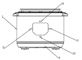
Fig. 3 is the structural representation of the shell of a kind of electric pressure cooking saucepan that makes things convenient for the control box dismounting of the present utility model.
Fig. 4 is the structure for amplifying schematic diagram at A place among Fig. 1.
Fig. 5 is the structure for amplifying schematic diagram at B place among Fig. 1.
Fig. 6 is the structure for amplifying schematic diagram at C place among Fig. 2.
Include among Fig. 1 to Fig. 6:
Shell 1, the first installing hole 11, the second installing hole 12, through hole 13;
Control box 2, the first buckle 21, L shaped clamping part 211;
The second buckle 22, screw 23;
Screw 3;
Bottom 4.
The specific embodiment
Below in conjunction with embodiment and accompanying drawing the utility model is described in further detail, but embodiment of the present utility model is not limited to this.
Embodiment of a kind of electric pressure cooking saucepan that makes things convenient for the control box dismounting of the present utility model such as Fig. 1 are to shown in Figure 6, include shell 1, the outer surface of shell 1 is equipped with control box 2, shell 1 offers for the installing hole that control box 2 is installed, installing hole includes the first installing hole 11 and the second installing hole 12, the left and right sides of one side of control box 2 relative installing holes is provided with the clamping that matches with the first installing hole 11 of the first buckle 21, the first buckles 21; Control box 2 is provided with the clamping that matches with the second installing hole 12 of the second buckle 22, the second buckles 22 with respect to the upper end of a side of installing hole.
Control box 2 is provided with for the screw 23 that screw 3 is installed with respect to the bottom of a side of installing hole, and shell 1 offers the through hole 13 that matches with screw 23, and screw 23 is connected with through hole 13 by screw 3, thereby control box 2 is locked in shell 1.
With reference to Fig. 3 and Fig. 6, the first buckle 21 includes L shaped clamping part 211, and L shaped clamping part 211 is connected in the first installing hole 11 downwards.
The first installing hole 11 is square installing hole, and when being convenient to install, L shaped clamping part 211 can successfully enter in the first installing hole 11, and is clamped in the first installing hole 11.
With reference to Fig. 3 and Fig. 4, the second buckle 22 includes L shaped clamping part, and L shaped clamping part is connected in the second installing hole 12 downwards.
The second installing hole 12 is square installing hole.
Concrete, through hole 13 is circular through hole 13.
The operation principle of the control box 2 of electric pressure cooking saucepan of the present utility model is as follows:
When installing, aligned in position with the first installing hole 11 on the first buckle 21 of control box 2 left and right sides and the electric pressure cooking saucepan shell 1, after the aligned in position with the second buckle 22 of control box 2 upper ends and the second installing hole 12, control box 2 is pressed into shell 1, again control box 2 is applied a downward power, the first buckle 21 and the second buckle 22 are inserted respectively in the first installing hole 11 and the second installing hole 12 simultaneously, behind the chucking, with screw 3 control box 2 and shell 1 are locked again, namely finish the installation of control box 2;
When dismounting, pull down first the bottom 4 of electric pressure cooking saucepan, then the screw 3 with locking screws out, and again control box 2 is applied thrust upwards, the first buckle 21 is separated with the second installing hole 12 with the first installing hole 11 respectively simultaneously with the second buckle 22, namely finish the dismounting of control box 2.
Thus, electric pressure cooker structure of the present utility model is simple, and control box 2 is easy to install, convenient disassembly, and is simple during operation, quick, time saving and energy saving, is convenient to maintenance and the replacing of control box 2, thereby saves production cost, and is conducive to electric pressure cooking saucepan popularizing on market.
Should be noted that at last; above embodiment is only in order to illustrate the technical solution of the utility model; but not to the restriction of the utility model protection domain; although with reference to preferred embodiment the utility model has been done to explain; those of ordinary skill in the art is to be understood that; can make amendment or be equal to replacement the technical solution of the utility model, and not break away from essence and the scope of technical solutions of the utility model.
Claims (7)
1. electric pressure cooking saucepan that makes things convenient for the control box dismounting, include shell, the outer surface of described shell is equipped with control box, it is characterized in that: described shell offers be used to the installing hole that described control box is installed, described installing hole includes the first installing hole and the second installing hole, the left and right sides of one side of the relatively described installing hole of described control box is provided with the first buckle, the clamping that matches with described the first installing hole of described the first buckle; Described control box is provided with the second buckle with respect to the upper end of a side of described installing hole, the clamping that matches with described the second installing hole of described the second buckle.
2. a kind of electric pressure cooking saucepan that makes things convenient for the control box dismounting according to claim 1, it is characterized in that: described control box is provided with for the screw that screw is installed with respect to the bottom of a side of described installing hole, described shell offers the through hole that matches with described screw, and described screw is connected with described through hole by screw.
3. a kind of electric pressure cooking saucepan that makes things convenient for the control box dismounting according to claim 1, it is characterized in that: described the first buckle includes L shaped clamping part, and described L shaped clamping part is connected in described the first installing hole downwards.
4. a kind of electric pressure cooking saucepan that makes things convenient for the control box dismounting according to claim 3, it is characterized in that: described the first installing hole is square installing hole.
5. a kind of electric pressure cooking saucepan that makes things convenient for the control box dismounting according to claim 1, it is characterized in that: described the second buckle includes L shaped clamping part, and described L shaped clamping part is connected in described the second installing hole downwards.
6. a kind of electric pressure cooking saucepan that makes things convenient for the control box dismounting according to claim 5, it is characterized in that: described the second installing hole is square installing hole.
7. a kind of electric pressure cooking saucepan that makes things convenient for the control box dismounting according to claim 2 is characterized in that: described through hole is circular through hole.
Priority Applications (1)
| Application Number | Priority Date | Filing Date | Title |
|---|---|---|---|
| CN 201220357194 CN202775822U (en) | 2012-07-23 | 2012-07-23 | Electric pressure cooker with conveniently demountable control box |
Applications Claiming Priority (1)
| Application Number | Priority Date | Filing Date | Title |
|---|---|---|---|
| CN 201220357194 CN202775822U (en) | 2012-07-23 | 2012-07-23 | Electric pressure cooker with conveniently demountable control box |
Publications (1)
| Publication Number | Publication Date |
|---|---|
| CN202775822U true CN202775822U (en) | 2013-03-13 |
Family
ID=47803192
Family Applications (1)
| Application Number | Title | Priority Date | Filing Date |
|---|---|---|---|
| CN 201220357194 Expired - Fee Related CN202775822U (en) | 2012-07-23 | 2012-07-23 | Electric pressure cooker with conveniently demountable control box |
Country Status (1)
| Country | Link |
|---|---|
| CN (1) | CN202775822U (en) |
Cited By (1)
| Publication number | Priority date | Publication date | Assignee | Title |
|---|---|---|---|---|
| CN110925910A (en) * | 2019-12-12 | 2020-03-27 | 合肥中车轨道交通车辆有限公司 | Plasma air purifier |
-
2012
- 2012-07-23 CN CN 201220357194 patent/CN202775822U/en not_active Expired - Fee Related
Cited By (1)
| Publication number | Priority date | Publication date | Assignee | Title |
|---|---|---|---|---|
| CN110925910A (en) * | 2019-12-12 | 2020-03-27 | 合肥中车轨道交通车辆有限公司 | Plasma air purifier |
Similar Documents
| Publication | Publication Date | Title |
|---|---|---|
| CN202126052U (en) | Pallet installation structure of temperature controller of air conditioner | |
| CN202775822U (en) | Electric pressure cooker with conveniently demountable control box | |
| CN203702787U (en) | Panel-type furniture connection invisible buckle | |
| CN203762840U (en) | Temperature controller and electric rice cooker provided with same | |
| CN204258709U (en) | Photovoltaic module fixture | |
| CN203461643U (en) | Self-locating elevator call box | |
| CN202978605U (en) | Integrated flameproof motor and frequency converter connecting device | |
| CN205543764U (en) | Switch board convenient to equipment | |
| CN203893550U (en) | Refrigerator | |
| CN204304157U (en) | The metal decking frame assembly of switch on wall or wall socket | |
| CN203435985U (en) | Detachable chair | |
| CN204894341U (en) | Work -clamping means | |
| CN201668140U (en) | Concave-convex plug sawtoothed fastener assembly structure for installing furniture | |
| CN209983818U (en) | Back lining, back shell quick assembly disassembly device | |
| CN203706023U (en) | Tablet personal computer with multifunctional fastener system | |
| CN214065337U (en) | Make things convenient for photovoltaic board to carry out photovoltaic support of dismouting | |
| CN203072278U (en) | Small cover for solar-water-heater control instrument | |
| CN201946451U (en) | Switch fixing structure | |
| CN201368494Y (en) | Heat radiating fan cover structure of electromagnetic oven | |
| CN201430385Y (en) | Fixing structure of bus plugging box | |
| CN202885039U (en) | Connecting structure between furnace feet and bottom shell in gas stove | |
| CN201310966Y (en) | Structure for connecting furnace end and bottom case of gas cooker | |
| CN2921142Y (en) | Integrated ceiling functional components mounting fastenings | |
| CN204115238U (en) | A kind of Novel push-draw casing of electric water heater | |
| CN202917352U (en) | A metal gate arc extinguishing device of a switch |
Legal Events
| Date | Code | Title | Description |
|---|---|---|---|
| C14 | Grant of patent or utility model | ||
| GR01 | Patent grant | ||
| CF01 | Termination of patent right due to non-payment of annual fee |
Granted publication date: 20130313 Termination date: 20150723 |
|
| EXPY | Termination of patent right or utility model |