CN202769550U - Light distribution structure of light-emitting diode (LED) lamp - Google Patents
Light distribution structure of light-emitting diode (LED) lamp Download PDFInfo
- Publication number
- CN202769550U CN202769550U CN2012203740589U CN201220374058U CN202769550U CN 202769550 U CN202769550 U CN 202769550U CN 2012203740589 U CN2012203740589 U CN 2012203740589U CN 201220374058 U CN201220374058 U CN 201220374058U CN 202769550 U CN202769550 U CN 202769550U
- Authority
- CN
- China
- Prior art keywords
- light
- led light
- led
- light source
- light distribution
- Prior art date
- Legal status (The legal status is an assumption and is not a legal conclusion. Google has not performed a legal analysis and makes no representation as to the accuracy of the status listed.)
- Expired - Fee Related
Links
Images
Landscapes
- Non-Portable Lighting Devices Or Systems Thereof (AREA)
Abstract
The utility model aims at disclosing a light distribution structure of a light-emitting diode (LED) lamp. The light distribution structure comprises a substrate, wherein an LED light source is arranged on the substrate, a reflecting cover is arranged at the bottom of the LED light source, and a light distribution cover is arranged on the outer side of the LED light source. Compared with the prior art, through functions of the reflecting cover and the light distribution cover which are arranged nearby the LED light source, light rays emitted by the LED light source are enabled to be evenly distributed and good in light distribution effect. The light distribution structure can be widely applied in LED lamps such as a mining lamp, a panel light, a bulb lamp, a fluorescent lamp, a lamp cup, a searchlight and a street lamp, and is simple in structure and quite practical. The purpose of the light distribution structure is achieved.
Description
Technical field
The utility model relates to a kind of light distribution structure, particularly a kind of light distribution structure that is applicable to the LED light fixture.
Background technology
The abbreviation of so-called LED(Light-emitting Diode) lamp refers to adopt the semiconductor light-emitting-diode technology as a kind of novel environment friendly illuminating product of light emitting source.The LED light fixture has the characteristics such as power and energy saving, easy to control, non-maintaining, safety and environmental protection and long service life, can reach 50000-100000 hour its service life, far surpasses 1000 hours and 10000 hours of fluorescent lamp of traditional osram lamp.LED must be the trend of future development as a kind of novel energy-saving and environmental protection green light source product.
The LED lamp except energy-saving and environmental protection, also will be considered the safety and comfort of lighting environment as a kind of illuminations simultaneously, and this just requires scientific and reasonable optical design, makes light fixture reach both efficient, energy-conservation, and good lighting quality is arranged again.
In the light characteristics of LED light fixture, mainly consider three aspects: the one, luminous intensity distribution performance, the 2nd, Luminaire efficiency, the 3rd, anti-dazzle characteristic.The Main Function of light fixture optical design is exactly to allow illumination distribute according to certain rules according to people's needs, Here it is light distribution characteristic.Good light distribution characteristic can the Effective Raise light fixture utilization rate, brightness is high, good uniformity, free from glare disturbs little to the light of surrounding enviroment simultaneously.
But the light distribution characteristic of existing LED light fixture is not very good, has a strong impact on whole light emission rate and the light distribution effect of LED light fixture.
Therefore, need especially a kind of light distribution structure of LED light fixture, to solve the above-mentioned existing problem that exists.
The utility model content
The purpose of this utility model is to provide a kind of light distribution structure of LED light fixture, for the deficiencies in the prior art, has all good characteristics of even light distribution effect of compact conformation, light distribution.
The technical problem that the utility model solves can realize by the following technical solutions:
A kind of light distribution structure of LED light fixture is characterized in that, it comprises a pedestal, is provided with a led light source at described pedestal, is provided with a reflection shield in the bottom of described led light source, in the arranged outside of described led light source one light distributing cap is arranged.
In an embodiment of the present utility model, described reflection shield comprises that the curved portions near described led light source reaches the line part that extends out from the end of described curved portions.
Further, described curved portions is parabolic shape.
In an embodiment of the present utility model, between described light distributing cap and led light source, also be provided with an interior light distributing cap, be provided with a transparent body that matches with described led light source on the top of described interior light distributing cap.
Further, the described transparent body is a light-distribution lens.
The light distribution structure of LED light fixture of the present utility model, compared with prior art, by near reflection shield and the light distributing cap effect the led light source is set, the distribution of light that led light source is come out is even, light distribution effect is good, can be widely used in the LED light fixtures such as bulkhead lamp capable, panel light, bulb lamp, fluorescent lamp, Lamp cup, searchlight and street lamp, and is simple in structure, very use, realize the purpose of this utility model.
Characteristics of the present utility model can be consulted the detailed description of the graphic and following better embodiment of this case and be obtained to be well understood to.
Description of drawings
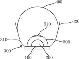
Fig. 1 is the structural representation of the light distribution structure of LED light fixture of the present utility model.
The specific embodiment
For technological means, creation characteristic that the utility model is realized, reach purpose and effect is easy to understand, below in conjunction with concrete diagram, further set forth the utility model.
As shown in Figure 1, the light distribution structure of LED light fixture of the present utility model, it comprises a pedestal 100, is provided with a led light source 200 at described pedestal 100, be provided with a reflection shield 300 in the bottom of described led light source 200, in the arranged outside of described led light source 200 light distributing cap 400 arranged.
In the utility model, described reflection shield 300 comprises that the curved portions 310 near described led light source 200 reaches the line part 320 that extends out from the end of described curved portions 310; Described curved portions 310 is parabolic shape.
In the utility model, between described light distributing cap 400 and led light source 200, also be provided with an interior light distributing cap 500, be provided with a transparent body 510 that matches with described led light source 200 on the top of described interior light distributing cap 500; The described transparent body 510 is a light-distribution lens.
During use, the light that led light source 200 produces, curved portions 310 and the line part 320 by reflection shield 300 reflexes to the light arrangement on the light distributing cap 400 first, distributed uniformly by light distributing cap 400; Interior light distributing cap 500 can further be strengthened the treatment effect to the light of led light source 200 generations, and the light that light distributing cap 400 is distributed is more even, better effects if.
The light distribution structure of LED light fixture of the present utility model can be widely used in the LED light fixtures such as bulkhead lamp capable, panel light, bulb lamp, fluorescent lamp, Lamp cup, searchlight and street lamp, and is simple in structure, very uses.
Above demonstration and described basic principle of the present utility model and principal character and advantage of the present utility model.The technical staff of the industry should understand; the utility model is not restricted to the described embodiments; that describes in above-described embodiment and the specification just illustrates principle of the present utility model; under the prerequisite that does not break away from the utility model spirit and scope; the utility model also has various changes and modifications; these changes and improvements all fall in claimed the utility model scope, and the claimed scope of the utility model is defined by appending claims and equivalent thereof.
Claims (5)
1. the light distribution structure of a LED light fixture is characterized in that, it comprises a pedestal, is provided with a led light source at described pedestal, is provided with a reflection shield in the bottom of described led light source, in the arranged outside of described led light source one light distributing cap is arranged.
2. the light distribution structure of LED light fixture as claimed in claim 1 is characterized in that, described reflection shield comprises that the curved portions near described led light source reaches the line part that extends out from the end of described curved portions.
3. the light distribution structure of LED light fixture as claimed in claim 2 is characterized in that, described curved portions is parabolic shape.
4. the light distribution structure of LED light fixture as claimed in claim 1 is characterized in that, also is provided with an interior light distributing cap between described light distributing cap and led light source, is provided with a transparent body that matches with described led light source on the top of described interior light distributing cap.
5. the light distribution structure of LED light fixture as claimed in claim 4 is characterized in that, the described transparent body is a light-distribution lens.
Priority Applications (1)
| Application Number | Priority Date | Filing Date | Title |
|---|---|---|---|
| CN2012203740589U CN202769550U (en) | 2012-07-31 | 2012-07-31 | Light distribution structure of light-emitting diode (LED) lamp |
Applications Claiming Priority (1)
| Application Number | Priority Date | Filing Date | Title |
|---|---|---|---|
| CN2012203740589U CN202769550U (en) | 2012-07-31 | 2012-07-31 | Light distribution structure of light-emitting diode (LED) lamp |
Publications (1)
| Publication Number | Publication Date |
|---|---|
| CN202769550U true CN202769550U (en) | 2013-03-06 |
Family
ID=47776118
Family Applications (1)
| Application Number | Title | Priority Date | Filing Date |
|---|---|---|---|
| CN2012203740589U Expired - Fee Related CN202769550U (en) | 2012-07-31 | 2012-07-31 | Light distribution structure of light-emitting diode (LED) lamp |
Country Status (1)
| Country | Link |
|---|---|
| CN (1) | CN202769550U (en) |
Cited By (1)
| Publication number | Priority date | Publication date | Assignee | Title |
|---|---|---|---|---|
| CN110805878A (en) * | 2018-08-06 | 2020-02-18 | 深圳视爵光电有限公司 | LED integral lighting lamp tube lampshade with lens light distribution function |
-
2012
- 2012-07-31 CN CN2012203740589U patent/CN202769550U/en not_active Expired - Fee Related
Cited By (1)
| Publication number | Priority date | Publication date | Assignee | Title |
|---|---|---|---|---|
| CN110805878A (en) * | 2018-08-06 | 2020-02-18 | 深圳视爵光电有限公司 | LED integral lighting lamp tube lampshade with lens light distribution function |
Similar Documents
| Publication | Publication Date | Title |
|---|---|---|
| CN203868945U (en) | Annular panel LED ceiling lamp | |
| CN204201712U (en) | A kind of LED road landscape lamp | |
| CN202769550U (en) | Light distribution structure of light-emitting diode (LED) lamp | |
| CN203453816U (en) | LED lamp bulb having large illumination angle | |
| CN102102818A (en) | Energy-saving environmental friendly lighting device | |
| CN201973617U (en) | Energy-saving ceiling lamp | |
| CN204739496U (en) | LED street lamp that throws light on | |
| CN204062580U (en) | A kind of LED lamp | |
| CN202812904U (en) | Light emitting diode (LED) lamp emitting spiral light | |
| CN203023952U (en) | Light-emitting diode (LED) laneway lamp | |
| CN203517642U (en) | Large-angle LED (light-emitting diode) bulb lamp | |
| CN203202675U (en) | LED bulb | |
| CN203384711U (en) | LED fluorescent lamp | |
| CN203298010U (en) | LED bulb lamp | |
| CN201428951Y (en) | Led lamp body | |
| CN203147410U (en) | LED lamp | |
| CN202484744U (en) | LED (Light-Emitting Diode) streetlamp | |
| CN202281059U (en) | LED lighting electric appliance | |
| CN204227265U (en) | A kind of novel HID and LED complementary type airplane landing taxiing light | |
| CN202812897U (en) | Light emitting diode (LED) lamp emitting multilayer annular wavy light | |
| CN202074306U (en) | Light emitting diode (LED) lamp | |
| CN202561478U (en) | Small lighting lamp | |
| CN202008036U (en) | LED candle lamp | |
| CN201126129Y (en) | Electrodeless lamp road lamp apparatus | |
| CN207378530U (en) | A kind of even smooth light bulbs of LED |
Legal Events
| Date | Code | Title | Description |
|---|---|---|---|
| C14 | Grant of patent or utility model | ||
| GR01 | Patent grant | ||
| C17 | Cessation of patent right | ||
| CF01 | Termination of patent right due to non-payment of annual fee |
Granted publication date: 20130306 Termination date: 20130731 |