CN202768989U - Novel adjusting valve body - Google Patents
Novel adjusting valve body Download PDFInfo
- Publication number
- CN202768989U CN202768989U CN 201220470156 CN201220470156U CN202768989U CN 202768989 U CN202768989 U CN 202768989U CN 201220470156 CN201220470156 CN 201220470156 CN 201220470156 U CN201220470156 U CN 201220470156U CN 202768989 U CN202768989 U CN 202768989U
- Authority
- CN
- China
- Prior art keywords
- valve body
- adjusting valve
- novel adjusting
- sides
- ear
- Prior art date
- Legal status (The legal status is an assumption and is not a legal conclusion. Google has not performed a legal analysis and makes no representation as to the accuracy of the status listed.)
- Expired - Fee Related
Links
Images
Abstract
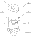
The utility model provides a novel adjusting valve body, and relates to the field of valve processing. The novel adjusting valve body comprises a valve body (1), an inlet (5) and an outlet (6). An opening hole (2) is formed at the top end of the valve body (1). A solid fixing lug (3) and a hollow fixing lug (4) are respectively arranged on two sides of the middle portion of the valve body (1). The inlet (5) is arranged in the middle of the outer wall of the valve body (1) and is placed between the solid fixing lug (3) and the hollow fixing lug (4). Fixing inserting buckles (7) are arranged on two sides of the valve body (1). The outlet (6) is placed between the two fixing inserting buckles (7). The novel adjusting valve body is simple in structure, ideal in using effect and capable of satisfying the requirements of modern industrial production.
Description
Technical field:
The utility model relates to the valve manufacture field, is specifically related to a kind of Novel regulating valve body.
Background technique:
Common regulation valve body is mostly simple in structure in the market, causes it to use function also comparatively single, and along with improving constantly of industrial level in these years, and traditional regulation valve body can not satisfy the needs of modern industry already far away.
The model utility content:
The purpose of this utility model provides a kind of Novel regulating valve body, and it can solve existing problem in the background technique effectively.
In order to solve the existing problem of background technique, the utility model is by the following technical solutions: it comprises valve body 1, import 5 and exports 6, the top of described valve body 1 is provided with perforate 2, the both sides at its middle part respectively are provided with fixedly ear 4 of a solid fixedly ear 3 and hollow, import 5 is installed in the outer wall middle part of valve body 1, be positioned at the fixedly centre of ear 4 of solid fixedly ear 3 and hollow, fixedly eye-splice 7 is installed in the both sides of valve body 1, and outlet 6 is at two fixedly between the eye-splice 7.
Described valve body 1 integral body is made for stainless steel material.
The utlity model has following beneficial effect: simple in structure, using effect is desirable, can satisfy the demand that modern industry is produced.
Description of drawings:
Fig. 1 is structural representation of the present utility model.
Embodiment:
Referring to Fig. 1, this embodiment is by the following technical solutions: it comprises valve body 1, import 5 and exports 6, the top of described valve body 1 is provided with perforate 2, the both sides at its middle part respectively are provided with fixedly ear 4 of a solid fixedly ear 3 and hollow, import 5 is installed in the outer wall middle part of valve body 1, be positioned at the fixedly centre of ear 4 of solid fixedly ear 3 and hollow, fixedly eye-splice 7 is installed in the both sides of valve body 1, and outlet 6 is at two fixedly between the eye-splice 7.
Described valve body 1 integral body is made for stainless steel material.
This embodiment has following beneficial effect: simple in structure, using effect is desirable, can satisfy the demand that modern industry is produced.
Claims (2)
1. Novel regulating valve body, it comprises valve body (1), import (5) and outlet (6), the top that it is characterized in that described valve body (1) is provided with perforate (2), the both sides at its middle part respectively are provided with fixedly ear (4) of a solid fixedly ear (3) and hollow, import (5) is installed in the outer wall middle part of valve body (1), be positioned at the fixedly centre of ear (4) of solid fixedly ear (3) and hollow, fixedly eye-splice (7) is installed in the both sides of valve body (1), and outlet (6) is positioned between two fixedly eye-splices (7).
2. a kind of Novel regulating valve body according to claim 1 is characterized in that described valve body (1) integral body is made for stainless steel material.
Priority Applications (1)
| Application Number | Priority Date | Filing Date | Title |
|---|---|---|---|
| CN 201220470156 CN202768989U (en) | 2012-09-17 | 2012-09-17 | Novel adjusting valve body |
Applications Claiming Priority (1)
| Application Number | Priority Date | Filing Date | Title |
|---|---|---|---|
| CN 201220470156 CN202768989U (en) | 2012-09-17 | 2012-09-17 | Novel adjusting valve body |
Publications (1)
| Publication Number | Publication Date |
|---|---|
| CN202768989U true CN202768989U (en) | 2013-03-06 |
Family
ID=47775564
Family Applications (1)
| Application Number | Title | Priority Date | Filing Date |
|---|---|---|---|
| CN 201220470156 Expired - Fee Related CN202768989U (en) | 2012-09-17 | 2012-09-17 | Novel adjusting valve body |
Country Status (1)
| Country | Link |
|---|---|
| CN (1) | CN202768989U (en) |
-
2012
- 2012-09-17 CN CN 201220470156 patent/CN202768989U/en not_active Expired - Fee Related
Similar Documents
| Publication | Publication Date | Title |
|---|---|---|
| CN202768989U (en) | Novel adjusting valve body | |
| CN202187389U (en) | Novel anti-spattering ceramic basin | |
| CN202834430U (en) | D-shaped steel pipe | |
| CN203167490U (en) | PCB board fixing structure | |
| CN103084109A (en) | Panting type sterile homogenizer | |
| CN202252195U (en) | Overflow valve with good opening and closing characteristic | |
| CN202329357U (en) | Plate hole for upper pipe plate of heat exchanger | |
| CN201996341U (en) | Magnetic slice type pot cover with adjustable air valve | |
| CN203311944U (en) | Electric appliance insulation accessory | |
| CN202418868U (en) | Novel adjustment valve | |
| CN203297789U (en) | Shower pipe | |
| CN202228732U (en) | Check valve | |
| CN201522024U (en) | Structural improvement of range hood volute casing | |
| CN201759376U (en) | Novel cooker handle of pressure cooker | |
| CN201724559U (en) | Launder of smelting furnace | |
| CN202372953U (en) | Mouse mat with bobbin winder | |
| CN202706326U (en) | Light steel keel | |
| CN202022724U (en) | Wrench-shaped bottle opener with sandglass | |
| CN202021568U (en) | Wrench with hourglass | |
| CN202619313U (en) | House-shaped plane with sandglass | |
| CN202217570U (en) | Three-phase distributing transformer with oval structure | |
| CN202816553U (en) | Novel electric reactor pulling plate | |
| CN203040326U (en) | Watering pot with music player | |
| CN202001694U (en) | Triangle valve | |
| CN201855755U (en) | Cuboid shower |
Legal Events
| Date | Code | Title | Description |
|---|---|---|---|
| C14 | Grant of patent or utility model | ||
| GR01 | Patent grant | ||
| CF01 | Termination of patent right due to non-payment of annual fee |
Granted publication date: 20130306 Termination date: 20150917 |
|
| EXPY | Termination of patent right or utility model |