CN202718461U - Three-rod handle lock - Google Patents
Three-rod handle lock Download PDFInfo
- Publication number
- CN202718461U CN202718461U CN 201220310914 CN201220310914U CN202718461U CN 202718461 U CN202718461 U CN 202718461U CN 201220310914 CN201220310914 CN 201220310914 CN 201220310914 U CN201220310914 U CN 201220310914U CN 202718461 U CN202718461 U CN 202718461U
- Authority
- CN
- China
- Prior art keywords
- holder
- rear door
- door
- blocking cover
- hand holding
- Prior art date
- Legal status (The legal status is an assumption and is not a legal conclusion. Google has not performed a legal analysis and makes no representation as to the accuracy of the status listed.)
- Expired - Lifetime
Links
Images


Landscapes
- Securing Of Glass Panes Or The Like (AREA)
Abstract
The utility model discloses a three-rod handle lock, which comprises a fixing seat, a front blocking cover, a rear blocking cover and handles. The handles are respectively arranged on the front blocking cover and the rear blocking cover. The three-rod handle lock is characterized in that a connection column is arranged in the front blocking cover, and the fixing seat is fixed with the connection column through a connection fastener and is also fixedly connected with the rear blocking cover through a fastening mechanism. Since the connection column is arranged in the front blocking cover, the fixing seat is fixed with the connection column through the connection fastener and the rear blocking cover is fixedly connected with the fixing seat through the fastening mechanism, the front blocking cover and the rear blocking cover can be prevented from being drilled on front faces to assemble screws for fixation, a handle can be attractive when being arranged on a door, and the variety of handles can be enriched.
Description
Technical field
The utility model relates to a kind of lockset, particularly a kind of three bar hand holding locks.
Background technology
Door is the requirement of household, all various hand holding locks can be housed above the door, is convenient for people to open the door and closes the door, and hand holding lock is an important component part of door, thereby the attractive in appearance of hand holding lock is very important for door integral body.
But the installation of some hand holding locks is to be fixed on the door by the screw of packing into of the hole on the face-piece front, and hole and screw can destroy the overall aesthetic of handle, thereby is necessary the handle for a kind of new door of defects design.
Summary of the invention
In order to overcome the deficiencies in the prior art, the utility model provides the hand holding lock of a kind of good looking appearance, practicality.
The technical scheme that its technical problem that solves the utility model adopts is:
A kind of three bar hand holding locks comprise holder, and front door, rear door and be arranged at respectively front door and handle that backstop covers is characterized in that: be provided with joint pin in the described front door, and holder is fixed by connecting securing member and joint pin; And holder is connected by retention mechanism and rear door.
Be provided with connecting screw hole in the described joint pin, holder is provided with the first connecting hole, and described connection securing member fixes front door and holder by the first connecting hole and connecting screw hole.
Described retention mechanism comprises the draw-in groove that is arranged on the holder, is arranged at the fastening screw on the rear door sidewall, and rear door snaps in draw-in groove by the screw that screws in fastening screw and is connected with holder.
Described rear door side wall inner surfaces is provided with boss, and described fastening screw runs through rear door sidewall and boss simultaneously.
The beneficial effects of the utility model are: be provided with joint pin in the front door of the present utility model, and holder fixes by connecting securing member and joint pin, then door is connected by retention mechanism and holder.Said structure has been avoided in the positive perforate of front door and rear door and the screw of packing into is fixed, thereby makes hand holding lock be installed on good looking appearance when upper, and has enriched the kind of hand holding lock.
Description of drawings
Below in conjunction with drawings and Examples the utility model is further specified:
Fig. 1 is explosive view of the present utility model;
Fig. 2 is the three-dimensional view of rear door;
Fig. 3 is assembled perspective view of the present utility model.
The specific embodiment
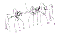
Referring to figs. 1 through Fig. 3, the utility model discloses a kind of three bar hand holding locks, comprise holder 1, front door 2, rear door 3 and be arranged at respectively handle 4 on front door 2 and the rear door 3, be provided with joint pin 5 in the front door 2, and holder 1 is fixing with joint pin 5 by connecting securing member 8; And holder 1 is connected by retention mechanism and rear door 3.
As shown in the figure, front door 2 with the concrete syndeton of holder 1 is, relatively be provided with two joint pins 5 on front door 2 inner surfaces, certainly joint pin 5 also can be set to three or four etc., be provided with connecting screw hole 6 in the joint pin 5, holder 1 is provided with first connecting hole 7 corresponding with connecting screw hole 6, connecting securing member 8 makes front door 2 fixing with holder 1 by the first connecting hole 7 and connecting screw hole 6, connect securing member 8 and adopted screw, certainly, above-mentioned is not unique, can adopt the connectors such as bolt yet.
As shown in the figure, the concrete syndeton of retention mechanism is, retention mechanism comprises the draw-in groove 9 that is arranged on the holder 1, draw-in groove 9 is provided with three, be arranged at the fastening screw 10 on rear door 3 sidewalls, fastening screw 10 also is provided with three, and rear door 3 snaps in draw-in groove 9 by the screw that screws in fastening screw 10 and is connected with holder 1, certainly, said structure does not consist of the restriction to the application, and said structure also can be, and on holder 1 sidewall screwed hole is set, the rear door 3 sidewall settings unthreaded hole corresponding with it penetrates unthreaded hole by screw and is connected with screwed hole and makes rear door 3 fixing with holder 1.In addition, rear door 3 side wall inner surfaces are provided with boss 11, and described fastening screw 10 runs through rear door 3 sidewalls and boss 11 simultaneously, play the effect of the local thickening of rear door 3 sidewalls by boss 11, thereby lengthened the length of fastening screw 10, made screw cooperate more firm with fastening screw 10.
Above-mentionedly just preferred embodiments more of the present utility model are illustrated and describe; but embodiment of the present utility model is not restricted to the described embodiments; as long as it reaches technique effect of the present utility model with essentially identical means, all should belong to protection domain of the present utility model.
Claims (4)
1. a bar hand holding lock comprises holder, and front door, rear door and be arranged at respectively front door and handle that backstop covers is characterized in that: be provided with joint pin in the described front door, and holder is fixed by connecting securing member and joint pin; And holder is connected by retention mechanism and rear door.
2. a kind of three bar hand holding locks according to claim 1, it is characterized in that: be provided with connecting screw hole in the described joint pin, holder is provided with the first connecting hole, and described connection securing member fixes front door and holder by the first connecting hole and connecting screw hole.
3. a kind of three bar hand holding locks according to claim 1, it is characterized in that: described retention mechanism comprises the draw-in groove that is arranged on the holder, is arranged at the fastening screw on the rear door sidewall, and rear door snaps in draw-in groove by the screw that screws in fastening screw and is connected with holder.
4. a kind of three bar hand holding locks according to claim 3, it is characterized in that: described rear door side wall inner surfaces is provided with boss, and described fastening screw runs through rear door sidewall and boss simultaneously.
Priority Applications (1)
| Application Number | Priority Date | Filing Date | Title |
|---|---|---|---|
| CN 201220310914 CN202718461U (en) | 2012-06-29 | 2012-06-29 | Three-rod handle lock |
Applications Claiming Priority (1)
| Application Number | Priority Date | Filing Date | Title |
|---|---|---|---|
| CN 201220310914 CN202718461U (en) | 2012-06-29 | 2012-06-29 | Three-rod handle lock |
Publications (1)
| Publication Number | Publication Date |
|---|---|
| CN202718461U true CN202718461U (en) | 2013-02-06 |
Family
ID=47620287
Family Applications (1)
| Application Number | Title | Priority Date | Filing Date |
|---|---|---|---|
| CN 201220310914 Expired - Lifetime CN202718461U (en) | 2012-06-29 | 2012-06-29 | Three-rod handle lock |
Country Status (1)
| Country | Link |
|---|---|
| CN (1) | CN202718461U (en) |
Cited By (2)
| Publication number | Priority date | Publication date | Assignee | Title |
|---|---|---|---|---|
| CN108397043A (en) * | 2018-04-04 | 2018-08-14 | 陈梅艳 | A kind of three rod type knob rotating discs |
| CN111622601A (en) * | 2020-07-01 | 2020-09-04 | 佛山市顺德区格瑞夫五金制品有限公司 | Door fitting |
-
2012
- 2012-06-29 CN CN 201220310914 patent/CN202718461U/en not_active Expired - Lifetime
Cited By (2)
| Publication number | Priority date | Publication date | Assignee | Title |
|---|---|---|---|---|
| CN108397043A (en) * | 2018-04-04 | 2018-08-14 | 陈梅艳 | A kind of three rod type knob rotating discs |
| CN111622601A (en) * | 2020-07-01 | 2020-09-04 | 佛山市顺德区格瑞夫五金制品有限公司 | Door fitting |
Similar Documents
| Publication | Publication Date | Title |
|---|---|---|
| RU2733458C2 (en) | Hidden connection system with front activation for lower part of furniture and furnishing elements | |
| CN202718461U (en) | Three-rod handle lock | |
| CN102865278A (en) | Self-locking bolt for furniture | |
| CN201321770Y (en) | Gate bolt | |
| CN206565620U (en) | A kind of furniture installs connection component | |
| CN202768576U (en) | Self locking screw used for furniture | |
| CN204850810U (en) | Latch | |
| CN203214512U (en) | Frame body connection piece structure | |
| CN204617241U (en) | A kind of key chain | |
| KR200396287Y1 (en) | A sash join structure of door | |
| CN203223449U (en) | Semiautomatic fitting safety pin | |
| CN201125636Y (en) | Single handle door board | |
| CN202047508U (en) | Connecting structure for horizontal keel and vertical keel of curtain wall | |
| CN201568720U (en) | Combined metal bracket structure | |
| CN202064739U (en) | Bolt used for door/window | |
| CN203296543U (en) | Door and window connecting piece | |
| CN204738602U (en) | Locking closure structure | |
| CN204060258U (en) | For the folding paper snap close that Furniture panel connects | |
| CN211082499U (en) | Furniture member plug-in connecting assembly | |
| CN201533670U (en) | Door cabinet | |
| CN202596280U (en) | Connecting piece for drilling-free door crack-penetrating lockset | |
| CN205688967U (en) | The locking transmission handle being easily installed | |
| CN201003336Y (en) | Lock | |
| CN202023810U (en) | Elastic piece combiner | |
| CN211397156U (en) | Finished wood door pocket mounting structure |
Legal Events
| Date | Code | Title | Description |
|---|---|---|---|
| C14 | Grant of patent or utility model | ||
| GR01 | Patent grant | ||
| TR01 | Transfer of patent right |
Effective date of registration: 20191227 Address after: No.16, Minyao Road, Dongsheng Town, Zhongshan City, Guangdong Province Patentee after: Zhongshan Longshang metal products Co.,Ltd. Address before: Six village 528400 Guangdong city of Zhongshan Province Dongsheng Town Guangfeng Yumin Wai Industrial Zone is dragon metal products factory Patentee before: Hu Chunlong |
|
| TR01 | Transfer of patent right | ||
| CX01 | Expiry of patent term |
Granted publication date: 20130206 |
|
| CX01 | Expiry of patent term |