CN202683794U - Square hole punching mold - Google Patents
Square hole punching mold Download PDFInfo
- Publication number
- CN202683794U CN202683794U CN 201220357409 CN201220357409U CN202683794U CN 202683794 U CN202683794 U CN 202683794U CN 201220357409 CN201220357409 CN 201220357409 CN 201220357409 U CN201220357409 U CN 201220357409U CN 202683794 U CN202683794 U CN 202683794U
- Authority
- CN
- China
- Prior art keywords
- square
- square hole
- pressure head
- utility
- punching mold
- Prior art date
- Legal status (The legal status is an assumption and is not a legal conclusion. Google has not performed a legal analysis and makes no representation as to the accuracy of the status listed.)
- Expired - Lifetime
Links
Images

Landscapes
- Perforating, Stamping-Out Or Severing By Means Other Than Cutting (AREA)
Abstract
The utility model discloses a square hole punching mold for machining an inner hole of a square tube. The square hole punching mold is characterized by comprising a punching seat and a square pressure head (4), wherein the punching seat comprises a table-board (3) arranged on a support column (6); and a square hole (7) and a positioning vertical plate (5) which is used for positioning are arranged on the table-board (3). The square hole punching mold has a simple structure and convenience in use.
Description
Technical field
The utility model relates to a kind of part processing mold, specifically a kind of square hole stamping mould.
Background technology
At present, in to the part processing that comprises square tube, the endoporus of square tube often deforms, so that affects the normal use of part.
Summary of the invention
The purpose of this utility model provides a kind of square hole stamping mould to inner hole of square processing.
The utility model is to adopt following technical scheme to realize its goal of the invention, a kind of square hole stamping mould, and it comprises punching press seat, square pressure head, and the punching press seat comprises the table top that is installed on the support column, and table top is provided with square hole and is used for the location riser of location.
Side's pressure head of the present utility model comprises guiding side's cone, typing square column and demoulding square column.
The height of support column of the present utility model is greater than the length of square pressure head.
Because adopt technique scheme, the utility model has been realized goal of the invention preferably, it is simple in structure, and is easy to use.
Description of drawings
Fig. 1 is structural representation of the present utility model;
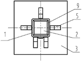
Fig. 2 is the top view of Fig. 1.
The specific embodiment
The utility model is described in further detail below in conjunction with drawings and Examples.
As seen from Figure 1, Figure 2, a kind of square hole stamping mould, it comprises punching press seat, square pressure head 4, and the punching press seat comprises the table top 3 that is installed on the support column 6, and table top 3 is provided with square hole 7 and is used for the location riser 5 of location.
The utility model side's pressure head 4 comprises guiding side's cone 8, typing square column 9 and demoulding square column 2.
The utility model is for ease of the demoulding, and the height of support column 6 is greater than the length of square pressure head 4, and the side's of being beneficial to pressure head 4 drops out from square hole 7.
When the utility model uses, the square tube 1 of need processing is put in the locating slot that is formed by location riser 5, owing to square hole 7 less than the appearance and size of square tube 1 size greater than endoporus, square pressure head 4 can pass through square hole 7, square tube 1 can not be passed through square hole 7.Side's pressure head 4 installs in square tube 1 endoporus, and the depression bar of forcing press removes 2 ones of the demoulding square columns of the side's of pressure pressure head 4, makes whole side's pressure head 4 pass the endoporus of square tube 1, by the inner hole extruding moulding of the typing square column 9 on the square pressure head 4 with square tube 1.
For the depression bar that prevents forcing press is pressed onto square tube 1, the height of location riser 5 needs the length greater than square tube 1.
Claims (3)
1. square hole stamping mould, it is characterized in that it comprises punching press seat, square pressure head (4), the punching press seat comprises the table top (3) that is installed on the support column (6), and table top (3) is provided with square hole (7) and is used for the location riser (5) of location.
2. square hole stamping mould according to claim 1, the side's of it is characterized in that pressure head (4) comprise guiding side's cone (8), typing square column (9) and demoulding square column (2).
3. square hole stamping mould according to claim 1 and 2 is characterized in that the height of support column (6) is greater than the length of square pressure head (4).
Priority Applications (1)
| Application Number | Priority Date | Filing Date | Title |
|---|---|---|---|
| CN 201220357409 CN202683794U (en) | 2012-07-23 | 2012-07-23 | Square hole punching mold |
Applications Claiming Priority (1)
| Application Number | Priority Date | Filing Date | Title |
|---|---|---|---|
| CN 201220357409 CN202683794U (en) | 2012-07-23 | 2012-07-23 | Square hole punching mold |
Publications (1)
| Publication Number | Publication Date |
|---|---|
| CN202683794U true CN202683794U (en) | 2013-01-23 |
Family
ID=47539466
Family Applications (1)
| Application Number | Title | Priority Date | Filing Date |
|---|---|---|---|
| CN 201220357409 Expired - Lifetime CN202683794U (en) | 2012-07-23 | 2012-07-23 | Square hole punching mold |
Country Status (1)
| Country | Link |
|---|---|
| CN (1) | CN202683794U (en) |
Cited By (1)
| Publication number | Priority date | Publication date | Assignee | Title |
|---|---|---|---|---|
| CN105268771A (en) * | 2015-10-29 | 2016-01-27 | 西安航空动力股份有限公司 | Device and method for rectifying hollow thin-walled castings |
-
2012
- 2012-07-23 CN CN 201220357409 patent/CN202683794U/en not_active Expired - Lifetime
Cited By (1)
| Publication number | Priority date | Publication date | Assignee | Title |
|---|---|---|---|---|
| CN105268771A (en) * | 2015-10-29 | 2016-01-27 | 西安航空动力股份有限公司 | Device and method for rectifying hollow thin-walled castings |
Similar Documents
| Publication | Publication Date | Title |
|---|---|---|
| CN202105914U (en) | Capacitor cover plate processing mold | |
| CN202206841U (en) | Hydraulic tea pressing machine | |
| CN201978996U (en) | Profiling stamping die | |
| CN202169331U (en) | Bushing processing die | |
| CN202683794U (en) | Square hole punching mold | |
| CN202045268U (en) | Small back plate forming die set | |
| CN201833525U (en) | Slide block tripping structure | |
| CN202169322U (en) | Molding device with upper die guide sleeve | |
| CN102380542A (en) | Punching die for machining and punching of mount support of front safety air bag | |
| CN203565654U (en) | Elastic piece continuous stamping die set | |
| CN202271677U (en) | Marking mould | |
| CN203621212U (en) | Hole-piercing punch | |
| CN202701176U (en) | Stamping device for automobile left suspended installation inner plate | |
| CN202291024U (en) | Glass bracket assembly reworking tooling | |
| CN206048354U (en) | A kind of mould of plastics structure | |
| CN203761223U (en) | Rotor spindle pressing die | |
| CN203356418U (en) | Core-replaceable fine blanking die set | |
| CN203665843U (en) | High-effect runner wire drawing prevention structure for mold | |
| CN202861336U (en) | Upper die core pressing plate | |
| CN203945540U (en) | Exterior trim product mold ejecting mechanism in automobile | |
| CN203862831U (en) | Gap bridge type forming die device | |
| CN202894020U (en) | High braking lamp support forming mould | |
| CN203566999U (en) | Air cylinder ejection device of foaming mould | |
| CN203599482U (en) | Lateral mold for solving bottom deformation of wheel rim | |
| CN202861119U (en) | Punching pin continuous die |
Legal Events
| Date | Code | Title | Description |
|---|---|---|---|
| C14 | Grant of patent or utility model | ||
| GR01 | Patent grant | ||
| CX01 | Expiry of patent term | ||
| CX01 | Expiry of patent term |
Granted publication date: 20130123 |