CN202668534U - 一种吊具储存架 - Google Patents
一种吊具储存架 Download PDFInfo
- Publication number
- CN202668534U CN202668534U CN 201220344347 CN201220344347U CN202668534U CN 202668534 U CN202668534 U CN 202668534U CN 201220344347 CN201220344347 CN 201220344347 CN 201220344347 U CN201220344347 U CN 201220344347U CN 202668534 U CN202668534 U CN 202668534U
- Authority
- CN
- China
- Prior art keywords
- supporting leg
- column
- arm
- suspension
- storage rack
- Prior art date
- Legal status (The legal status is an assumption and is not a legal conclusion. Google has not performed a legal analysis and makes no representation as to the accuracy of the status listed.)
- Expired - Fee Related
Links
Images

Abstract
本实用新型属于储存工艺领域,提出一种吊具储存架,所述的吊具储存架包括有立柱(4)、支腿、横臂(1)、悬挂臂(2)和定位销(3);所述的立柱(4)为两个,两个立柱(4)的下端分别固定在所对应的支腿上;两个立柱(4)的上端通过横臂(1)连接;在所述的横臂(1)上设置多个用以悬挂吊臂的悬挂臂(2);所述的悬挂臂(2)为一端向外并向上伸出的结构;在悬挂臂(2)伸出端的端头设置定位销(3)。本实用新型提出的一种吊具储存架,悬挂臂用于吊具的悬挂,对吊具进行分类、定点存放,避免了现场的混乱,立柱用来支撑悬挂臂保持一定的空间高度,使吊具存放整齐,同时提高了生产效率。
Description
技术领域
本实用新型属于吊具储存领域,主要涉及一种吊具储存架,用于转向架生产中的吊具储存。
背景技术
在生产制作转向架时,对转向架进行吊运,需要一些吊具,然而用后储存没有标准要求,造成现场较为混乱,影响整个现场的生产秩序,无法满足精益生产线的要求。
实用新型内容
为解决上述技术问题,本实用新型的目的是提出一种吊具储存架。
本实用新型完成其上述目的采用如下技术方案:
一种吊具储存架,所述的吊具储存架包括有立柱、支腿、横臂、悬挂臂和定位销;所述的立柱为两个,两个立柱的下端分别固定在所对应的支腿上;两个立柱的上端通过横臂连接;在所述的横臂上设置多个用以悬挂吊臂的悬挂臂;所述的悬挂臂为一端向外并向上伸出的结构;在悬挂臂伸出端的端头设置定位销。
对应每个立柱所述的支腿为两个,其中支腿Ⅰ与立柱垂直设置,立柱固定在支腿Ⅰ的一端,所述支腿Ⅱ的一端与立柱连接,另一端与支腿Ⅰ连接。
本实用新型提出的一种吊具储存架,悬挂臂用于吊具的悬挂,对吊具进行分类、定点存放,避免了现场的混乱,立柱用来支撑悬挂臂保持一定的空间高度,使吊具存放整齐,同时提高了生产效率。
附图说明
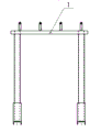
图1为本实用新型的结构示意图。
图2 为图1的侧视图。
图中:1、横臂,2、悬挂壁,3、定位销,4、立柱,5、支腿Ⅱ,6、支腿Ⅰ。
具体实施方式
结合附图和具体实施例对本实用新型加以说明:
如图1、图2所示,一种吊具储存架,所述的吊具储存架包括有立柱4、支腿、横臂1、悬挂臂2和定位销3;所述的立柱4为两个,两个立柱4的下端分别固定在所对应的支腿上;两个立柱4的上端通过横臂1连接;在所述的横臂1上设置多个用以悬挂吊臂的悬挂臂2;所述的悬挂臂2为一端向外并向上伸出的结构;在悬挂臂2伸出端的端头设置定位销3。
对应每个立柱所述的支腿为两个,其中支腿Ⅰ6与立柱4垂直设置,立柱4固定在支腿Ⅰ6的一端,所述支腿Ⅱ5的一端与立柱4连接,另一端与支腿Ⅰ6连接。
在进行吊具存放时,将吊具分类存放于悬挂臂上,存放到固定的区域,在使用时可简洁命明了的得到相应的吊具,此时可保证现场的整洁,满足使用要求,大大提高生产效率。
Claims (2)
1.一种吊具储存架,其特征在于:所述的吊具储存架包括有立柱(4)、支腿、横臂(1)、悬挂臂(2)和定位销(3);所述的立柱(4)为两个,两个立柱(4)的下端分别固定在所对应的支腿上;两个立柱(4)的上端通过横臂(1)连接;在所述的横臂(1)上设置多个用以悬挂吊臂的悬挂臂(2);所述的悬挂臂(2)为一端向外并向上伸出的结构;在悬挂臂(2)伸出端的端头设置定位销(3)。
2.根据权利要求1所述的一种吊具储存架,其特征在于:对应每个立柱所述的支腿为两个,其中支腿Ⅰ(6)与立柱(4)垂直设置,立柱(4)固定在支腿Ⅰ(6)的一端,所述支腿Ⅱ(5)的一端与立柱(4)连接,另一端与支腿Ⅰ(6)连接。
Priority Applications (1)
| Application Number | Priority Date | Filing Date | Title |
|---|---|---|---|
| CN 201220344347 CN202668534U (zh) | 2012-07-17 | 2012-07-17 | 一种吊具储存架 |
Applications Claiming Priority (1)
| Application Number | Priority Date | Filing Date | Title |
|---|---|---|---|
| CN 201220344347 CN202668534U (zh) | 2012-07-17 | 2012-07-17 | 一种吊具储存架 |
Publications (1)
| Publication Number | Publication Date |
|---|---|
| CN202668534U true CN202668534U (zh) | 2013-01-16 |
Family
ID=47489467
Family Applications (1)
| Application Number | Title | Priority Date | Filing Date |
|---|---|---|---|
| CN 201220344347 Expired - Fee Related CN202668534U (zh) | 2012-07-17 | 2012-07-17 | 一种吊具储存架 |
Country Status (1)
| Country | Link |
|---|---|
| CN (1) | CN202668534U (zh) |
Cited By (3)
| Publication number | Priority date | Publication date | Assignee | Title |
|---|---|---|---|---|
| CN105881481A (zh) * | 2016-06-23 | 2016-08-24 | 合肥市神雕起重机械有限公司 | 一种吊钩存放装置 |
| CN108772808A (zh) * | 2018-07-09 | 2018-11-09 | 中车洛阳机车有限公司 | 一种折弯检测样板的储存工装 |
| CN109205075A (zh) * | 2017-07-03 | 2019-01-15 | 天津港第四港埠有限公司 | 叉车叉齿吊具摘挂存放支架 |
-
2012
- 2012-07-17 CN CN 201220344347 patent/CN202668534U/zh not_active Expired - Fee Related
Cited By (4)
| Publication number | Priority date | Publication date | Assignee | Title |
|---|---|---|---|---|
| CN105881481A (zh) * | 2016-06-23 | 2016-08-24 | 合肥市神雕起重机械有限公司 | 一种吊钩存放装置 |
| CN109205075A (zh) * | 2017-07-03 | 2019-01-15 | 天津港第四港埠有限公司 | 叉车叉齿吊具摘挂存放支架 |
| CN109205075B (zh) * | 2017-07-03 | 2024-01-05 | 天津港第四港埠有限公司 | 叉车叉齿吊具摘挂存放支架 |
| CN108772808A (zh) * | 2018-07-09 | 2018-11-09 | 中车洛阳机车有限公司 | 一种折弯检测样板的储存工装 |
Similar Documents
| Publication | Publication Date | Title |
|---|---|---|
| CN202668534U (zh) | 一种吊具储存架 | |
| CN201734426U (zh) | 一种挂衣架 | |
| CN205433195U (zh) | 一种组合衣架 | |
| CN201770876U (zh) | 一种挂衣架 | |
| CN204708548U (zh) | 一种可同时悬挂多件衣服的衣架 | |
| CN202168706U (zh) | 多用途衣架挂钩 | |
| CN203106671U (zh) | 便携式吸盘挂钩 | |
| CN202959717U (zh) | 一种铁艺服装展示架 | |
| CN202739601U (zh) | 环杆 | |
| CN202212301U (zh) | 轨道平垫块喷漆挂具 | |
| CN201968582U (zh) | 新型毛巾架 | |
| CN202604465U (zh) | 多功能衣架 | |
| CN202044050U (zh) | 一种挂衣架 | |
| CN202287604U (zh) | 多功能衣架 | |
| CN201612450U (zh) | 一种晒鞋架 | |
| CN201683649U (zh) | 一种挂衣架 | |
| CN201734440U (zh) | 一种衣架 | |
| CN203088608U (zh) | 一种衣架 | |
| CN201767676U (zh) | 一种衣架 | |
| CN202086225U (zh) | 新型衣架 | |
| CN203000422U (zh) | 可挂袜衣架 | |
| CN205133766U (zh) | 高效挂镀槽 | |
| CN202035945U (zh) | 多功能裤架 | |
| CN202287624U (zh) | 新型晾衣架 | |
| CN202941607U (zh) | 一种用于挂置双人吊床的支架 |
Legal Events
| Date | Code | Title | Description |
|---|---|---|---|
| C14 | Grant of patent or utility model | ||
| GR01 | Patent grant | ||
| C56 | Change in the name or address of the patentee | ||
| CP01 | Change in the name or title of a patent holder |
Address after: Qiming Chanhe Hui District in Henan province Luoyang City Road 471002 No. 2 Patentee after: CRRC LUOYANG CO., LTD. Address before: Qiming Chanhe Hui District in Henan province Luoyang City Road 471002 No. 2 Patentee before: CSR Luoyang Locomotive Co., Ltd. |
|
| CF01 | Termination of patent right due to non-payment of annual fee | ||
| CF01 | Termination of patent right due to non-payment of annual fee |
Granted publication date: 20130116 Termination date: 20170717 |