CN202661201U - Heat allocation system for remote meter reading - Google Patents
Heat allocation system for remote meter reading Download PDFInfo
- Publication number
- CN202661201U CN202661201U CN 201220357172 CN201220357172U CN202661201U CN 202661201 U CN202661201 U CN 202661201U CN 201220357172 CN201220357172 CN 201220357172 CN 201220357172 U CN201220357172 U CN 201220357172U CN 202661201 U CN202661201 U CN 202661201U
- Authority
- CN
- China
- Prior art keywords
- heat
- calorimeter
- water
- control system
- flow
- Prior art date
- Legal status (The legal status is an assumption and is not a legal conclusion. Google has not performed a legal analysis and makes no representation as to the accuracy of the status listed.)
- Expired - Fee Related
Links
Images

Abstract
The utility model relates to the technical field of heating metering, in particular to a heat allocation system for remote meter reading. The heat allocation system is characterized by comprising a remote control system, a general packet radio service (GPRS) network, data concentrators, building total heat meters and unit user terminals. The remote control system is in wireless connection with the data concentrators through the GPRS network, and the data concentrators are connected with the building total heat meters which are connected with the unit user terminals through water feed pipe networks respectively, so that the heat of all the building total heat meters and the unit user terminals is transmitted back to the remote control system in a form of electrical signals through the data concentrators and the GPRS network respectively. Building total heat meter heat values, unit user terminal heat meter heat values, allocation values and charges are displayed on a server interface of the remote control system, so that the heat metering between heat supplying companies and unit users is reasonable, effects of being checkable with evidences, saving energy and metering accurately can be achieved, and reliable theoretical bases are provided for metering and charging of heat supply.
Description
Technical field
The utility model relates to a kind of heating metering technical field, specifically a kind of remote meter reading heat sharing system to the public pipe network heat of heating.
Background technology
As everyone knows, take the building or heat supply company during as heat clearing point, the calorimeter of this position provides the heat clearing foundation of heat, and resident family's English is interpreted as heat sharing in the building, each household should arrange corresponding measurement mechanism to carry out sharing between the family to the heat consumption of entire building, has reached the calculating that thermal loss is assigned to the family.
At present, the allocation scheme of heat metering has two kinds of metering methods usually: calorimeter measurement Law and make-and-break time area metering method.The calorimeter measurement Law can measure the heat that use at minute family, deficiency is: although make-and-break time area metering method can calculate the heat exhaustion of whole pipe network, can't rationally will but can't accurate measurement arrive each family for the loss of public pipe network in the heat transmission accurately.In the central heating metering, in order to accomplish real household metering, namely " use how much heat; what hand over take ", except the family is carried out the accurate measurement with heat, how many heat transmission losses between also will calculating from the heating network to user is, because this part loss is produced by household heat supplying, so should be born by the user who enjoys heat supply (annotate: that firmly builds section builds that (2008) No. 183 literary compositions in city " national heat supply process guide rule " propose).And present heat metering be because the thermal loss during to the transmission of public pipe network can't calculate the family, so this part loss is all born by heat supply department, this is that shortage is rational to a certain extent.
Summary of the invention
The purpose of this utility model is to solve above-mentioned the deficiencies in the prior art, the house lead in heat that provides a kind of heat metering not only can calculate each family, simultaneously also the thermal loss owing to the public pipe network of heat supply can be accurate to each family, so that the fairer and more reasonable remote meter reading heat sharing system of heat.
The technical scheme that its technical matters that solves the utility model adopts is:
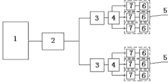
A kind of remote meter reading heat sharing system, it is characterized in that comprising tele-control system, GPRS network, data concentrator, a building total heat scale and unit users terminal, tele-control system is through GPRS network and data concentrator wireless connections, data concentrator is connected with a building calorimeter, each building calorimeter is connected with the unit users terminal through the water inlet pipe network respectively, so that the heat of each building total heat scale and unit users terminal calorimeter with the form of electric signal respectively through data concentrator, GPRS network passes back to tele-control system, server interface at tele-control system shows a building total amount of heat exterior heat value and unit users terminal calorimeter calorie value, described unit users terminal is provided with temperature-sensing valve and family calorimeter, the family is installed in respectively on the water inlet pipe with calorimeter and temperature-sensing valve, calorimeter comprises the flow of inlet water sensor, the inflow temperature sensor, return water temperature sensor and integraph, by the flow of inlet water sensor flow of the water of flowing through in the water inlet pipe is sent to integraph with the form of electric signal, integraph gathers and calculates the acquisition stream value, be transferred in the server of tele-control system through GPRS network by data concentrator, the usefulness enthusiasm condition of display unit user terminal and share hot expense situation on the system interface of server, make the heat metering between heat supply company and the unit users more be tending towards reasonable, reach and have good grounds, save energy, the accurate effect of metering also provides reliable theoretical foundation for the heat metering charge.
The calorimeter of the terminal of unit users described in the utility model can adopt two-flow meter calorimeter, two-flow meter calorimeter comprises the flow of inlet water sensor, the circling water flow rate sensor, the inflow temperature sensor, return water temperature sensor and integraph, the flow of inlet water sensor is connected with integraph through data line respectively with the circling water flow rate sensor, the inflow temperature sensor is connected with integraph through data line respectively with the return water temperature sensor, by the flow of inlet water sensor flow of the water of flowing through in the water inlet pipe and circling water flow rate sensor are sent to integraph with the form of electric signal respectively with the flow of the water of flowing through in the return pipe, integraph is by gathering the acquisition stream value, comparison and calculating, on integraph, show simultaneously inflow and backwater amount, also be transferred in the server of tele-control system through GPRS network by data concentrator simultaneously, the usefulness enthusiasm condition of display unit user terminal and dehydration situation on the system interface of server, not only guaranteed the normal operation of heating network, also measure by inflow and the two of backwater amount to unit users simultaneously, the use heat that made system's accurate measurement and share heat, make the heat metering between heat supply company and the unit users more be tending towards reasonable, reach and have good grounds, save energy, the accurate effect of metering also provides reliable theoretical foundation for the heat metering charge.
Effect of the present utility model:
1) this heat supply heat metering method has effectively carried out Computation for apportionment to the transmission thermal loss of public pipe network, has accurately calculated each family.
2) heat supply department can fully according to by with the heat charge, simultaneously for each charge provides adequately and reasonably foundation, be convenient to also can help heat supply department to reach energy-conservation effect for the user accepts.
3) for the user, real having accomplished on the meaning fully " use how much heat, what take in friendship " simultaneously also can be from realizing the awareness of saving energy that promotes the user.
The utility model is applicable to all heating networks, from heat supply and two angles of user, reaches the energy-conservation purpose of promotion, also provides reliable theoretical foundation for the heat metering charge.
Description of drawings
Fig. 1 is structural representation of the present utility model.
Fig. 2 is the structural representation of the utility model two-flow meter calorimeter.
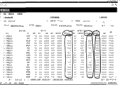
Fig. 3 is the surface chart of embodiment of the present utility model.
Reference numeral: tele-control system 1, GPRS network 2, data concentrator 3, a building total heat scale 4, unit users terminal 5, temperature-sensing valve 6, calorimeter 7, flow of inlet water sensor 8, inflow temperature sensor 9, return water temperature sensor 10 and integraph 11, circling water flow rate sensor 12, water inlet pipe 13, return pipe 14.
Embodiment
Below in conjunction with accompanying drawing the utility model is further specified:
As shown in drawings, a kind of remote meter reading heat sharing system, it is characterized in that comprising tele-control system 1, GPRS network 2, data concentrator 3, a building total heat scale 4 and unit users terminal 5, tele-control system 1 comprises server and internet, tele-control system 1 is through GPRS network 2 and data concentrator 3 wireless connections, data concentrator 3 is connected with a building calorimeter 4, each building calorimeter 4 is connected with unit users terminal 5 through the water inlet pipe network respectively, so that the heat of each building total heat scale 4 and unit users terminal 5 calorimeters with the form of electric signal respectively through data concentrator 3, GPRS network 2 passes back to tele-control system 1, server system interface at tele-control system 1 shows building total heat scale 4 calorie value and unit users terminal 5 calorimeter calorie values, described unit users terminal 5 is provided with temperature-sensing valve 6 and family calorimeter 7, the family is installed in respectively on the water inlet pipe with calorimeter 7 and temperature-sensing valve 6, calorimeter 7 comprises flow of inlet water sensor 8, inflow temperature sensor 9, return water temperature sensor 10 and integraph 11, by flow of inlet water sensor 8 flow of the water of flowing through in the water inlet pipe is sent to integraph 11 with the form of electric signal, 11 pairs of acquisition stream values of integraph gather and calculate, be transferred in the server of tele-control system 1 through GPRS network 2 by data concentrator 3, the usefulness enthusiasm condition of display unit user terminal 5 and share hot expense situation on the system interface of server, make the heat metering between heat supply company and the unit users more be tending towards reasonable, reach and have good grounds, save energy, the accurate effect of metering, also provide reliable theoretical foundation for the heat metering charge
It is as follows that it specifically shares step:
1) heat supply department is when heat supply begins, and tele-control system 1 server reads the numerical value Q of a building total heat scale 4 by data concentrator 3
0(take the i family as example, the little tabular value of its correspondence is q with calorimeter numerical value with all families
I0); Σ Δ Qqtt0i,
2) at any time t of heating, tele-control system 1 server reads the numerical value Q of a building total heat scale by data concentrator 3
T(take the i family as example, the little tabular value of its correspondence is q with calorimeter numerical value with all families
It),
3) so arrive till the t moment, tele-control system 1 server is Δ Q by the heat numerical value that data concentrator 3 reads a building total heat scale
T=Q
T-Q
0, (take the i family as example, the family of its correspondence is Δ q with calorimeter metering numerical value with calorimeter numerical value at all families
It=q
It-q
I0),
4) system-computed goes out the summation q that calorimeter is used at t all families of the moment
T=Σ Δ q
It,
5) the thermal loss value of a t moment building public pipe network of interior heat supply is Δ q
T=Δ Q
T-q
T,
6) t constantly in the building that should bear of i user public pipe network thermal loss be Δ q
i=Δ q
T* Δ q
It/ q
T,
7) t moment i user's is actual in heat Δ q
I is total=Δ q
It+ Δ q
i,
Wherein: Q
0The calorie value of an expression building calorimeter,
Q
I0The calorimeter calorie value of expression unit users terminal,
T represents heating time,
Q
TBe illustrated in the calorie value of a building calorimeter in the t time,
Q
ItBe illustrated in the heat of using of interior unit users i of t time,
Δ Q
TThe expression heat supply t time, the gross calorific value of a building calorimeter,
Δ q
TThe thermal loss value of public pipe network in the expression heat supply t time building,
Δ q
ItThe expression heat supply t time, the calorie value of unit users calorimeter,
Δ q
iThe thermal loss of public pipe network takes in the expression t time quantum user i apportioned building,
Δ q
I is totalThe reality of expression t time quantum user i is always used heat.
The calorimeter 7 of the terminal of unit users described in the utility model 5 can adopt two-flow meter calorimeter 7, two-flow meter calorimeter 7 comprises flow of inlet water sensor 8, circling water flow rate sensor 12, inflow temperature sensor 9, return water temperature sensor 10 and integraph 11, flow of inlet water sensor 8 is connected with integraph 11 through data line respectively with circling water flow rate sensor 12, inflow temperature sensor 9 is connected with integraph 11 through data line respectively with return water temperature sensor 10, by flow of inlet water sensor 8 flow of the water of flowing through in the water inlet pipe 13 and circling water flow rate sensor 12 are sent to integraph 11 with the form of electric signal respectively with the flow of the water of flowing through in the return pipe 14, integraph 11 is by gathering the acquisition stream value, comparison and calculating, on integraph 11, show simultaneously inflow and backwater amount, also be transferred in the server of tele-control system 1 through GPRS network 2 by data concentrator 3 simultaneously, the usefulness enthusiasm condition of display unit user terminal 5 and dehydration situation on the system interface of server, not only guaranteed the normal operation of heating network, also measure by inflow and the two of backwater amount to unit users simultaneously, the use heat that made system's accurate measurement and share heat, make the heat metering between heat supply company and the unit users more be tending towards reasonable, reach and have good grounds, save energy, the accurate effect of metering, also provide reliable theoretical foundation for heat metering charge, shared the interface and computing method are the same.
Embodiment: B Thermal Corp is when being the beginning heat supply of No. 27 building, and numerical value 6599999.92 and all families of reading a building calorimeter 77770001 are seen Fig. 3 for details with calorimeter numerical value.
Effect of the present utility model:
1) this heat supply heat metering method has effectively carried out Computation for apportionment to the transmission thermal loss of public pipe network, has accurately calculated each family.
2) heat supply department can fully by with the heat charge, simultaneously for each charge provides adequately and reasonably foundation, be convenient to also can help heat supply department to reach energy-conservation effect for the user accepts.
3) for the user, real having accomplished on the meaning fully " use how much heat, what take in friendship " simultaneously also can be from realizing the awareness of saving energy that promotes the user.
The utility model is applicable to all heating networks, from heat supply and two angles of user, reaches the energy-conservation purpose of promotion, also provides reliable theoretical foundation for the heat metering charge.
Claims (2)
1. remote meter reading heat sharing system, it is characterized in that comprising tele-control system, GPRS network, data concentrator, a building total heat scale and unit users terminal, tele-control system is through GPRS network and data concentrator wireless connections, data concentrator is connected with a building calorimeter, each building calorimeter is connected with the unit users terminal through the water inlet pipe network respectively, so that the heat of each building total heat scale and unit users terminal calorimeter with the form of electric signal respectively through data concentrator, GPRS network passes back to tele-control system, server interface at tele-control system shows a building total amount of heat exterior heat value and unit users terminal calorimeter calorie value, described unit users terminal is provided with temperature-sensing valve and family calorimeter, the family is installed in respectively on the water inlet pipe with calorimeter and temperature-sensing valve, calorimeter comprises the flow of inlet water sensor, the inflow temperature sensor, return water temperature sensor and integraph, by the flow of inlet water sensor flow of the water of flowing through in the water inlet pipe and circling water flow rate sensor are sent to integraph with the form of electric signal respectively with the flow of the water of flowing through in the return pipe, integraph gathers and calculates the acquisition stream value, be transferred in the server of tele-control system the usefulness enthusiasm condition of display unit user terminal and share hot expense situation on the system interface of server through GPRS network by data concentrator.
2. a kind of remote meter reading heat sharing according to claim 1 system, the calorimeter that it is characterized in that described unit users terminal adopts two-flow meter calorimeter, two-flow meter calorimeter comprises flow of inlet water sensor, circling water flow rate sensor, inflow temperature sensor, return water temperature sensor and integraph, the flow of inlet water sensor is connected with integraph through data line respectively with the circling water flow rate sensor, and the inflow temperature sensor is connected with integraph through data line respectively with the return water temperature sensor.
Priority Applications (1)
| Application Number | Priority Date | Filing Date | Title |
|---|---|---|---|
| CN 201220357172 CN202661201U (en) | 2012-07-23 | 2012-07-23 | Heat allocation system for remote meter reading |
Applications Claiming Priority (1)
| Application Number | Priority Date | Filing Date | Title |
|---|---|---|---|
| CN 201220357172 CN202661201U (en) | 2012-07-23 | 2012-07-23 | Heat allocation system for remote meter reading |
Publications (1)
| Publication Number | Publication Date |
|---|---|
| CN202661201U true CN202661201U (en) | 2013-01-09 |
Family
ID=47456102
Family Applications (1)
| Application Number | Title | Priority Date | Filing Date |
|---|---|---|---|
| CN 201220357172 Expired - Fee Related CN202661201U (en) | 2012-07-23 | 2012-07-23 | Heat allocation system for remote meter reading |
Country Status (1)
| Country | Link |
|---|---|
| CN (1) | CN202661201U (en) |
Cited By (5)
| Publication number | Priority date | Publication date | Assignee | Title |
|---|---|---|---|---|
| CN105605668A (en) * | 2016-03-08 | 2016-05-25 | 成都众山科技有限公司 | Water-saving heat meter with convenience in remote monitoring |
| CN106322502A (en) * | 2016-08-24 | 2017-01-11 | 连云港腾越电子科技有限公司 | Full-automatic control system for centralized-heating household metering |
| CN110243016A (en) * | 2018-03-09 | 2019-09-17 | 江苏迈拓智能仪表有限公司 | A kind of constant current heating metering method |
| CN113295300A (en) * | 2021-06-08 | 2021-08-24 | 迈拓仪表股份有限公司 | Constant-current heating metering method |
| CN115371129A (en) * | 2022-10-25 | 2022-11-22 | 山东辰智电子科技有限公司 | Thermal metering system, thermal metering method, storage medium and electronic device |
-
2012
- 2012-07-23 CN CN 201220357172 patent/CN202661201U/en not_active Expired - Fee Related
Cited By (7)
| Publication number | Priority date | Publication date | Assignee | Title |
|---|---|---|---|---|
| CN105605668A (en) * | 2016-03-08 | 2016-05-25 | 成都众山科技有限公司 | Water-saving heat meter with convenience in remote monitoring |
| CN106322502A (en) * | 2016-08-24 | 2017-01-11 | 连云港腾越电子科技有限公司 | Full-automatic control system for centralized-heating household metering |
| CN110243016A (en) * | 2018-03-09 | 2019-09-17 | 江苏迈拓智能仪表有限公司 | A kind of constant current heating metering method |
| CN113295300A (en) * | 2021-06-08 | 2021-08-24 | 迈拓仪表股份有限公司 | Constant-current heating metering method |
| CN113295300B (en) * | 2021-06-08 | 2024-02-09 | 迈拓仪表股份有限公司 | Constant-current heating metering method |
| CN115371129A (en) * | 2022-10-25 | 2022-11-22 | 山东辰智电子科技有限公司 | Thermal metering system, thermal metering method, storage medium and electronic device |
| CN115371129B (en) * | 2022-10-25 | 2023-02-28 | 山东辰智电子科技有限公司 | Thermal metering system, thermal metering method, storage medium and electronic device |
Similar Documents
| Publication | Publication Date | Title |
|---|---|---|
| CN202661201U (en) | Heat allocation system for remote meter reading | |
| CN102494810A (en) | Separate household heating measurement device of serial single-pipe connection type heating pipe network system and method | |
| CN204494705U (en) | Air-conditioning energy consumption detection system | |
| CN201637516U (en) | Integral electromagnetic heat meter | |
| CN203929882U (en) | Distributed power source access user bidirectional measuring and monitoring system | |
| CN204758062U (en) | Intelligent teletransmission gas of thing networking table | |
| CN102768086A (en) | Remote meter reading heat allocation system and method | |
| CN104678167B (en) | A kind of intelligent electric energy meter and utility meter kilowatt meter reading-out system | |
| CN203190519U (en) | Concentrator circuit for heating system | |
| CN103093549B (en) | Heating charging method and charging device thereof | |
| CN101290252B (en) | User heating caloric metering system | |
| CN202614425U (en) | Double-flowmeter ultrasonic calorimeter | |
| CN102706485A (en) | Ultrasonic heat meter with double flowmeters | |
| CN201368783Y (en) | Non-magnetic heat meter based on ZigBee wireless network | |
| CN209945588U (en) | Internet of things heat meter | |
| CN203052849U (en) | Data collection and heat metering accounting management system | |
| CN203455404U (en) | Electric energy measuring device applied in wind power plant | |
| CN203432719U (en) | Heat supply metering system for centralized heat distribution meter | |
| CN202795570U (en) | Centralized heating metering temperature control Internet of Things monitoring device | |
| CN202660638U (en) | Remote automatic water steal and leakage prevention control system | |
| CN110578511A (en) | Temperature difference type oil well oil yield measuring device and method | |
| CN204987225U (en) | Heat supply pipe network control and charging system | |
| CN201622141U (en) | Heat energy metering device | |
| CN204988406U (en) | Fuel gas metering device and system based on power communication | |
| CN110332606A (en) | A kind of heating system and its heat supply method |
Legal Events
| Date | Code | Title | Description |
|---|---|---|---|
| C14 | Grant of patent or utility model | ||
| GR01 | Patent grant | ||
| CF01 | Termination of patent right due to non-payment of annual fee |
Granted publication date: 20130109 Termination date: 20140723 |
|
| EXPY | Termination of patent right or utility model |