CN202659519U - Internal pressurized multistage shield pump for conveying easily gasifying medium - Google Patents
Internal pressurized multistage shield pump for conveying easily gasifying medium Download PDFInfo
- Publication number
- CN202659519U CN202659519U CN201220297215.0U CN201220297215U CN202659519U CN 202659519 U CN202659519 U CN 202659519U CN 201220297215 U CN201220297215 U CN 201220297215U CN 202659519 U CN202659519 U CN 202659519U
- Authority
- CN
- China
- Prior art keywords
- pump
- rotor shaft
- bearing block
- rear bearing
- motor
- Prior art date
- Legal status (The legal status is an assumption and is not a legal conclusion. Google has not performed a legal analysis and makes no representation as to the accuracy of the status listed.)
- Expired - Lifetime
Links
Images


Classifications
-
- F—MECHANICAL ENGINEERING; LIGHTING; HEATING; WEAPONS; BLASTING
- F04—POSITIVE - DISPLACEMENT MACHINES FOR LIQUIDS; PUMPS FOR LIQUIDS OR ELASTIC FLUIDS
- F04D—NON-POSITIVE-DISPLACEMENT PUMPS
- F04D29/00—Details, component parts, or accessories
- F04D29/58—Cooling; Heating; Diminishing heat transfer
- F04D29/5806—Cooling the drive system
-
- F—MECHANICAL ENGINEERING; LIGHTING; HEATING; WEAPONS; BLASTING
- F04—POSITIVE - DISPLACEMENT MACHINES FOR LIQUIDS; PUMPS FOR LIQUIDS OR ELASTIC FLUIDS
- F04D—NON-POSITIVE-DISPLACEMENT PUMPS
- F04D13/00—Pumping installations or systems
- F04D13/02—Units comprising pumps and their driving means
- F04D13/06—Units comprising pumps and their driving means the pump being electrically driven
- F04D13/0606—Canned motor pumps
-
- F—MECHANICAL ENGINEERING; LIGHTING; HEATING; WEAPONS; BLASTING
- F05—INDEXING SCHEMES RELATING TO ENGINES OR PUMPS IN VARIOUS SUBCLASSES OF CLASSES F01-F04
- F05D—INDEXING SCHEME FOR ASPECTS RELATING TO NON-POSITIVE-DISPLACEMENT MACHINES OR ENGINES, GAS-TURBINES OR JET-PROPULSION PLANTS
- F05D2240/00—Components
- F05D2240/60—Shafts
- F05D2240/61—Hollow
Abstract
The utility model relates to an internal pressurized multistage shield pump for conveying an easily gasifying medium. The internal pressurized multistage shield pump comprises a pump body and a motor body and is characterized in that a pressurizing auxiliary impeller is arranged on a rotor shaft of the motor body, a central slot hole is disposed on the rotor shaft from the rear end face to the installation position of the auxiliary impeller, one end of the central slot hole is opened and communicated with an inner cavity of a rear bearing block, the other end of central slot hole is communicated with a radial cross liquid through hole disposed on the body of the rotor shaft, a pump rear section outer cylinder of the pump body is communicated with the rear bearing block through an outer circulation pipe, and air releasing valves are positioned at the highest point of the cylinder body of a pump front section outer cylinder of the pump body and on the upper portion of the rear bearing block. The internal pressurized multistage shield pump can be used for lubricating and cooling bearings. Circulation fluid of the cooling motor can return to a pump outlet smoothly to prevent a circulating medium from gasifying, the quantity of the circulating medium returning to an impeller low-pressure area of the pump body can be controlled, and the impeller is prevented from cavitation.
Description
Technical field
The utility model belongs to the canned motorpump technical field, is specifically related to a kind of multi-stage shield pump of carrying easy gasifying medium.
Background technique
Usually select reverse circulation type multi-stage shield pump when at present, using multiple shielded electric-pump to carry easy gasifying medium.Reverse circulation type multi-stage shield pump is in service to bearing cooling, lubricated, and to the liquid flow direction that the cooling of motor is adopted be: liquid enters from pump part entrance, most of liquid is discharged by the pump section port, a small amount of liquid arrives in the motor cavity through front-end bearing pedestal, and finally arrive at rear bearing block, then draw via the contrary circulation pipe arrangement in outside that is provided on the rear bearing block, finally be external to liquid suction tank (Fig. 5).Because its structural requirement adopts the working site of reverse circulation type multi-stage shield pump that contrary circulation pipe arrangement must be installed, and for pipe arrangement following requirement is arranged: 1, contrary circulation pipe arrangement total head (drag overall)≤0.1 times pump liquid lift; 2, contrary circulation loop must connect to the vapour phase district that sucks flow container.But in actual use, owing to being subjected to the restriction of field condition or client's specific (special) requirements, have following problem: 1, contrary circulation pipe arrangement requirement is high, and equipment uses strongly professional, and use is difficult for, cost is high; 2, in some occasion, there are contrary circulation pipe arrangement length or pipeline complicated layout, contrary circulation pipe arrangement drag overall makes contrary circular flow not enough, therefore make the pump cisco unity malfunction greater than 0.1 times of lift; 3, without the pipe arrangement space, can't finish contrary circulation pipe arrangement; Or being used field condition to limit, circulating liquid can't be got back to the vapour phase district of suction flow container etc.
Because the contrary circulation pipe arrangement complexity of reverse circulation type multi-stage shield pump is high, the waste construction material increases cost, take up room, and some field condition can't reach contrary circulation pipe arrangement installation requirement at all.
The model utility content
High in order to solve the contrary circulation pipe arrangement complexity that has reverse circulation type multi-stage shield pump now, the waste construction material, increase cost, large problem takes up room, the utility model passes through architecture advances, a kind of multi-stage shield pump with internal pressurization mechanism is provided, can perfectly solves the work of this kind situation electric pump.The key of dealing with problems is to guarantee to be used for lubricated, cooling bearing, and the smooth and easy pump discharge of getting back to of the circulating liquid of cooling motor prevents the circulatory mediator gasification, and the amount of the circulatory mediator of impeller low pressure area is got back in simultaneously control, prevents the impeller cavitation.
The technological scheme that the utility model adopts is:
A kind of internal pressurization type multi-stage shield pump of carrying easy gasifying medium comprises the pump housing that is comprised of pump intake 1, pump leading portion urceolus 2, pump discharge 4 and pump back segment urceolus 5; Be provided with first order impeller sets 10 and second level impeller sets 13 in the pump housing; The described pump housing is connecting the motor body that is comprised of motor casing, front-end bearing pedestal 6, rear bearing block 8, stator module 15 and rotor assembly 16; The rotor shaft 19 of described rotor assembly 16 is located at the center of motor body by fore bearing 14 and rear bearing 18, the output terminal of rotor shaft 19 extends in the pump housing outward;
One side neck body of the pump back segment urceolus 5 of the described pump housing is provided with outer circulating tube inlet union 11, the axial centre of the rear bearing block 8 of described motor body is provided with outer circulating tube outlet connection 12, is communicated with by outer circulating tube 7 between described outer circulating tube inlet union 11 and the outer circulating tube outlet connection 12;
Be provided with axial centre slotted hole 20 in the described rotor shaft 19 rear end axle bodies, one end opening of center slotted hole 20 is positioned at the ear end face of rotor shaft 19 and communicates with the rear bearing block inner chamber of motor body, the other end of center slotted hole 20 is crossed fluid through-hole 21 with the radially cross that rotor shaft 19 rear end axle bodies are provided with and is communicated with, and sheathed sub-propeller 17 on rotor shaft 19 axle bodies at fluid through-hole 21 places crossed in described cross.
One side neck body of the pump leading portion urceolus 2 of the described pump housing is provided with first row air valve 3, and first row air valve 3 is positioned at the peak of pump leading portion urceolus 2 cylindrical shells.
Top one side of the rear bearing block 8 of described motor body is provided with second row air valve 9.
Useful technique effect of the present utility model embodies in the following areas:
1, the outer circulating tube by linking to each other between pump back segment urceolus and the rear bearing block, guaranteed the complete cycle path of circulating liquid in motor, thereby need not to derive from rear bearing block the circulating liquid of the motor of flowing through, so need not to install additional at the scene contrary circulation pipe arrangement in the engineering pipe arrangement, reduced the pipe arrangement of working site, reduce construction cost, and saved the space;
2, by the supercharging of the sub-propeller on the rotor assembly to circulating liquid, guaranteed to arrive at via outer circulating tube from pump back segment urceolus the circulating liquid of rear bearing block inner chamber, can be along the smooth and easy entrance that is back to pump back segment place second level impeller sets (anti-impeller) of motor internal, and effectively prevented the generation of motor internal circulatory mediator gasification by pressurized effect;
3, by at the height point place of pump leading portion urceolus and the height point place of motor rear bearing block two outlet valves being set, guaranteed the gas that may pile up or produce in the pump work is got rid of, guaranteed reliable, the safe operation of pump.
Description of drawings
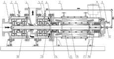
Fig. 1 is the utility model structural representation (take 4 impeller multi-stage shield pumps as example).
Fig. 2 is the side view of Fig. 1.
Fig. 3 is rotor assembly rear end part schematic diagram of the present utility model.
Fig. 4 is sub-propeller structural representation of the present utility model.
Fig. 5 is existing contrary loop structure multi-stage shield pump structural representation (take 4 impeller multi-stage shield pumps as example).
Sequence number among the upper figure: 1 pump intake, 2 pump leading portion urceolus, 3 first row air valves, 4 pump discharges, 5 pump back segment urceolus, 6 front-end bearing pedestals, 7 outer circulating tubes, 8 rear bearing blocks, 9, the second row air valve, 10 first order impeller sets, 11 outer circulating tube inlet union, 12 outer circulating tube outlet connections, 13 second level impeller sets, 14 fore bearings, 15 stator modules, 16 rotor assembly, 17 sub-propellers, 18 rear bearings, 19 rotor shafts, 20 center slotted holes, fluid through-hole crossed in 21 crosses, 22 sub-propeller cover plates, 23 terminal boxes, 24 contrary circulation pipe arrangements.
Embodiment
Below in conjunction with accompanying drawing, the utility model is further described by embodiment.
Embodiment:
As depicted in figs. 1 and 2, this carries the internal pressurization type multi-stage shield pump of easy gasifying medium, and the pump housing of pump part mainly comprises pump intake 1, pump leading portion urceolus 2, pump discharge 4, pump back segment urceolus 5, is sleeved on rotor shaft 19 output terminals second level impeller sets 13, first order impeller sets 10; The motor body of motor part mainly comprises motor casing, stator module 15 and rotor assembly 16, and front-end bearing pedestal 6 and rear bearing block 8 are equipped with respectively in the motor casing two ends, install respectively fore bearing 14 and rear bearing 18 in the axle bearing.Its characteristics are: pump back segment urceolus 5 one side neck bodies are provided with outer circulating tube inlet union 11, and rear bearing block 8 axial centre are provided with outer circulating tube outlet connection 12, and both are communicated with by outer circulating tube 7; Pump leading portion urceolus 2 peaks are installed first row air valve 3 in addition; Second row air valve 9 is installed at high some place, the top of rear bearing block 8.
As shown in Figure 3 and Figure 4, the rotor shaft 19 of rotor assembly axially is drilled with center slotted hole 20 in the rear end, and hole depth arrives the mounting point of sub-propeller 17; Sub-propeller 17 is installed in the rear portion of rotor shaft 19, and fluid through-hole 21 crossed in the radially cross that the axle body of mounting point is provided with, and an end opening of center slotted hole 20 communicates with the rear bearing block inner chamber of motor body, and the other end is crossed fluid through-hole 21 with cross and is communicated with; Take the sub-propeller of 4 impellers as example, be laid with four back blades on the inner side surface of sub-propeller 17 and be cross and arrange, the outer side surface of sub-propeller 17 is provided with sub-propeller cover plate 22.
Working principle: shown in the direction of arrow among Fig. 1, easily gasified liquid is entered by pump intake, by first order impeller sets 10, arrive pump back segment urceolus 5 positions, wherein most liquid can through front-end bearing pedestal 6 the place aheads and through second level impeller sets (anti-impeller) 13, finally arrive at the pump discharge of pump water exit end 4.Sub-fraction liquid can be at pump back segment urceolus 5 punishment streams through outer circulating tube 7, arrive at the inner chamber of rear bearing block 8, and the center slotted hole 20 of process axle back segment, flow out from crossing the fluid through-hole 21 near the cross of sub-propeller 17, through the supercharging of sub-propeller 17, the space of flow through stator module and rotor assembly, and flow to the place ahead of front-end bearing pedestal 6 from the slit of fore bearing 14, stroke is drawn from pump, gets back to the complete cycle in the pump.The utility model has saved outside contrary circulation pipe arrangement than existing contrary cycle multistage canned motorpump.
The liquid supercharging that 17 pairs of sub-propellers flow through provides circulating liquid power on the one hand, drives it and flows to front-end bearing pedestal 6 places from sub-propeller, on the other hand to the increase of fluid pressure, so that this liquid when the motor of flowing through cools off, in the situation of being heated, is compared the more difficult gasification of existing apparatus.
Claims (3)
1. an internal pressurization type multi-stage shield pump of carrying easy gasifying medium comprises the pump housing that is comprised of pump intake (1), pump leading portion urceolus (2), pump discharge (4) and pump back segment urceolus (5); Be provided with first order impeller sets (10) and second level impeller sets (13) in the pump housing; The described pump housing is connecting the motor body that is comprised of motor casing, front-end bearing pedestal (6), rear bearing block (8), stator module (15) and rotor assembly (16); The rotor shaft (19) of described rotor assembly (16) is located at the center of motor body by fore bearing (14) and rear bearing (18), the output terminal of rotor shaft (19) extends in the pump housing outward; It is characterized in that:
One side neck body of the pump back segment urceolus (5) of the described pump housing is provided with outer circulating tube inlet union (11), the axial centre of the rear bearing block of described motor body (8) is provided with outer circulating tube outlet connection (12), is communicated with by outer circulating tube (7) between described outer circulating tube inlet union (11) and the outer circulating tube outlet connection (12);
Be provided with axial centre slotted hole (20) in the axle body of described rotor shaft (19) rear end, one end opening of center slotted hole (20) is positioned at the ear end face of rotor shaft (19) and communicates with the rear bearing block inner chamber of motor body, the other end of center slotted hole (20) is crossed fluid through-hole (21) with the radially cross that rotor shaft (19) rear end axle body is provided with and is communicated with, and sheathed sub-propeller (17) on rotor shaft (19) axle body that fluid through-hole (21) locates crossed in described cross.
2. a kind of internal pressurization type multi-stage shield pump of carrying easy gasifying medium according to claim 1, it is characterized in that: a side neck body of the pump leading portion urceolus (2) of the described pump housing is provided with first row air valve (3), and first row air valve (3) is positioned at the peak of pump leading portion urceolus (2) cylindrical shell.
3. a kind of internal pressurization type multi-stage shield pump of carrying easy gasifying medium according to claim 1, it is characterized in that: top one side of the rear bearing block of described motor body (8) is provided with second row air valve (9).
Priority Applications (1)
| Application Number | Priority Date | Filing Date | Title |
|---|---|---|---|
| CN201220297215.0U CN202659519U (en) | 2012-06-25 | 2012-06-25 | Internal pressurized multistage shield pump for conveying easily gasifying medium |
Applications Claiming Priority (1)
| Application Number | Priority Date | Filing Date | Title |
|---|---|---|---|
| CN201220297215.0U CN202659519U (en) | 2012-06-25 | 2012-06-25 | Internal pressurized multistage shield pump for conveying easily gasifying medium |
Publications (1)
| Publication Number | Publication Date |
|---|---|
| CN202659519U true CN202659519U (en) | 2013-01-09 |
Family
ID=47454428
Family Applications (1)
| Application Number | Title | Priority Date | Filing Date |
|---|---|---|---|
| CN201220297215.0U Expired - Lifetime CN202659519U (en) | 2012-06-25 | 2012-06-25 | Internal pressurized multistage shield pump for conveying easily gasifying medium |
Country Status (1)
| Country | Link |
|---|---|
| CN (1) | CN202659519U (en) |
Cited By (8)
| Publication number | Priority date | Publication date | Assignee | Title |
|---|---|---|---|---|
| KR20170005773A (en) * | 2015-07-06 | 2017-01-16 | 가부시키가이샤 에바라 세이사꾸쇼 | Fan scrubber and vacuum pump apparatus |
| CN106907328A (en) * | 2016-08-30 | 2017-06-30 | 合肥新沪屏蔽泵有限公司 | One kind conveying high-melting-point medium heat-preserving type multistage ultra-high temperature shielding pump |
| CN107076154A (en) * | 2014-06-24 | 2017-08-18 | 斯特林工业咨询有限公司 | Side-channel pump |
| CN107084159A (en) * | 2017-03-15 | 2017-08-22 | 安徽六国化工股份有限公司 | A kind of external circulation shielding pump |
| CN108087290A (en) * | 2017-12-27 | 2018-05-29 | 合肥新沪屏蔽泵有限公司 | A kind of high-pressure masked pump of chemical-process conveying |
| CN111810439A (en) * | 2020-08-18 | 2020-10-23 | 大连海密梯克泵业有限公司 | Anti-dead-bearing structure of serial multistage pump sliding bearing and multistage canned motor pump |
| CN111927787A (en) * | 2020-08-18 | 2020-11-13 | 大连海密梯克泵业有限公司 | Multistage canned motor pump with inner loop hole |
| CN114893414A (en) * | 2022-05-11 | 2022-08-12 | 湖北航天技术研究院总体设计所 | Shielding type electric precompression pump of liquid rocket engine |
-
2012
- 2012-06-25 CN CN201220297215.0U patent/CN202659519U/en not_active Expired - Lifetime
Cited By (12)
| Publication number | Priority date | Publication date | Assignee | Title |
|---|---|---|---|---|
| CN107076154A (en) * | 2014-06-24 | 2017-08-18 | 斯特林工业咨询有限公司 | Side-channel pump |
| US10704565B2 (en) | 2014-06-24 | 2020-07-07 | Sterling Industry Consult Gmbh | Side-channel pump |
| KR20170005773A (en) * | 2015-07-06 | 2017-01-16 | 가부시키가이샤 에바라 세이사꾸쇼 | Fan scrubber and vacuum pump apparatus |
| CN106337844A (en) * | 2015-07-06 | 2017-01-18 | 株式会社荏原制作所 | Fan Scrubber And Vacuum Pump Apparatus |
| TWI718161B (en) * | 2015-07-06 | 2021-02-11 | 日商荏原製作所股份有限公司 | Fan scrubber and vacuum pump apparatus |
| KR102326732B1 (en) * | 2015-07-06 | 2021-11-17 | 가부시키가이샤 에바라 세이사꾸쇼 | Fan scrubber and vacuum pump apparatus |
| CN106907328A (en) * | 2016-08-30 | 2017-06-30 | 合肥新沪屏蔽泵有限公司 | One kind conveying high-melting-point medium heat-preserving type multistage ultra-high temperature shielding pump |
| CN107084159A (en) * | 2017-03-15 | 2017-08-22 | 安徽六国化工股份有限公司 | A kind of external circulation shielding pump |
| CN108087290A (en) * | 2017-12-27 | 2018-05-29 | 合肥新沪屏蔽泵有限公司 | A kind of high-pressure masked pump of chemical-process conveying |
| CN111810439A (en) * | 2020-08-18 | 2020-10-23 | 大连海密梯克泵业有限公司 | Anti-dead-bearing structure of serial multistage pump sliding bearing and multistage canned motor pump |
| CN111927787A (en) * | 2020-08-18 | 2020-11-13 | 大连海密梯克泵业有限公司 | Multistage canned motor pump with inner loop hole |
| CN114893414A (en) * | 2022-05-11 | 2022-08-12 | 湖北航天技术研究院总体设计所 | Shielding type electric precompression pump of liquid rocket engine |
Similar Documents
| Publication | Publication Date | Title |
|---|---|---|
| CN202659519U (en) | Internal pressurized multistage shield pump for conveying easily gasifying medium | |
| CN101846085A (en) | Frequency conversion high-speed wet type submersible pump | |
| CN102943831B (en) | Hydrodynamic retarder | |
| CN108412778A (en) | A kind of motor preposition formula submersed three-flow pump | |
| CN206943014U (en) | A kind of barrel pocket type extraction pump structure | |
| CN104564717A (en) | Direct driven high-speed turbine vacuum pump and operation method thereof | |
| CN205895628U (en) | High -lift multistage deep well subaqueous pump | |
| CN208982361U (en) | A kind of welded type volute pump | |
| CN104100537A (en) | LNG (liquefied natural gas) immersed centrifugal pump | |
| CN205937147U (en) | Liquid cooling multistage centrifugal pump | |
| CN201535254U (en) | Peripheral canned pump | |
| CN207297392U (en) | Small flow canned motor pump | |
| CN202926927U (en) | Hydraulic buffer | |
| CN106762854A (en) | A kind of anti-cavitation double feed inlet double-suction multi-stage pump | |
| CN101210567A (en) | Horizontal multistage stainless steel centrifugal pump | |
| CN206647315U (en) | A kind of external circulation shielding pump | |
| CN207568930U (en) | A kind of mobile pump vehicle fluid pressure type mixed-flow pump | |
| CN208330756U (en) | A kind of motor preposition formula submersed three-flow pump | |
| CN202091206U (en) | Combined type tubular pump device of water outlet structure | |
| CN108869306A (en) | Horizontal double sucking pump is opened in double containment level | |
| CN204805099U (en) | Bulb formula helical blade through -flow pump | |
| CN206593504U (en) | A kind of jetting stream vacuum system transformed for energy saving for power plants | |
| CN208057428U (en) | Easy-to-dismount centrifugal pump | |
| CN112628146A (en) | Multistage double suction pump with vertical structure | |
| CN206221345U (en) | The auxiliary blade wheel structure of stove water pump |
Legal Events
| Date | Code | Title | Description |
|---|---|---|---|
| C14 | Grant of patent or utility model | ||
| GR01 | Patent grant | ||
| C41 | Transfer of patent application or patent right or utility model | ||
| TR01 | Transfer of patent right |
Effective date of registration: 20130531 Address after: 230088 Anhui city of Hefei province high tech Zone Technology Park Bai Yan Yang Road No. 1 Patentee after: Hefei Xinhu Canned Motor Pump Co.,Ltd. Address before: 230088 Anhui city of Hefei province high tech Zone Technology Park Bai Yan Yang Road No. 1 Patentee before: HEFEI XINHU CANNED MOTOR PUMP Co.,Ltd. |
|
| CX01 | Expiry of patent term |
Granted publication date: 20130109 |
|
| CX01 | Expiry of patent term |