CN202629541U - Automatic lubricating grease injecting device - Google Patents
Automatic lubricating grease injecting device Download PDFInfo
- Publication number
- CN202629541U CN202629541U CN2012202371534U CN201220237153U CN202629541U CN 202629541 U CN202629541 U CN 202629541U CN 2012202371534 U CN2012202371534 U CN 2012202371534U CN 201220237153 U CN201220237153 U CN 201220237153U CN 202629541 U CN202629541 U CN 202629541U
- Authority
- CN
- China
- Prior art keywords
- lubricating grease
- lubricating
- lubricating cup
- filling device
- automatic filling
- Prior art date
- Legal status (The legal status is an assumption and is not a legal conclusion. Google has not performed a legal analysis and makes no representation as to the accuracy of the status listed.)
- Expired - Lifetime
Links
Images

Abstract
The utility model relates to an automatic lubricating grease injecting device, in particular to a vibration type automatic lubricating grease injecting device applied to a hydraulic crushing hammer. The automatic lubricating grease injecting device comprises a valve body assembly and a lubricating grease cup assembly, wherein the valve body assembly comprises a valve block and a lubricating grease output mechanism, a groove is arranged in the middle of the upper surface of the valve block, the lubricating grease output mechanism is arranged inside the valve block, the lubricating grease cup assembly comprises a grease cup and a negative pressure providing mechanism, the negative pressure providing mechanism is fixed on the valve block, and the grease cup is arranged in the groove of the valve block. The automatic lubricating grease injecting device is capable of completely replacing a manual injection method, avoids halt for injection, saves labor force, and is increased in production efficiency; and meanwhile, lubricating grease is uniformly and continuously injected, so that a front housing part and a drill rod of a crushing hammer are lubricated uniformly, therefore, the service life of the crushing hammer is prolonged, and the production cost is lowered.
Description
Technical field
The utility model relates to a kind of lubricating grease automatic filling device, particularly a kind of oscillatory type lubricating grease automatic filling device that is applied on the hydraulic breaking hammer.
Background technique
Hydraulic breaking hammer is a kind of and the matching used engineering disintegrating apparatus of hydraulic shovel, its in the course of the work, drill steel need be done high frequency, high-intensity to-and-fro motion.The size of mechanical friction has determined the length in quartering hammer working life between hydraulic crushing hammar drill rod and the fore shell lining, therefore, and the lubricated very key before the quartering hammer between the case member.
At present, most of hydraulic breaking hammer lubricating grease generally adopts artificial method of annotating, but there is following defective in artificial filling: 1. during artificial the filling, quartering hammer need quit work, and has a strong impact on manufacturing efficiency; 2. artificial filling can only disposable a small amount of adding, very easily causes quartering hammer fore shell and drill steel lubricated inhomogeneous because of grease adding is insufficient; 3. owing to be manual operation, in practical work process, operator possibly forget filling on time, cause case member and drill steel wearing and tearing aggravation before the quartering hammer, shorten quartering hammer working life.
The model utility content
The utility model provides a kind of oscillatory type lubricating grease automatic filling device, replaces artificial filling, has overcome the various defectives that adopt artificial charging method and cause, and has prolonged the working life of quartering hammer, has reduced cost of production.
The technological scheme that the utility model solve the technical problem is following: a kind of oscillatory type lubricating grease automatic filling device comprises valve body assembly and lubricating grease lubricating cup assembly; Wherein, said valve body assembly comprises valve piece and lubricating grease output mechanism, and said valve piece upper surface middle part has groove, and it is inner that said lubricating grease output mechanism is installed on said valve piece; Said lubricating grease lubricating cup assembly comprises that lubricating cup and negative pressure provide mechanism, and said negative pressure provides mechanism to be fixed on the said valve piece, and said lubricating cup places in the groove of said valve piece.
The beneficial effect of the utility model is: can substitute artificial filling fully, avoid shutting down filling, save manpower, improve manufacturing efficiency; Simultaneously, grease adding evenly continues, and makes before the quartering hammer case member and drill steel evenly lubricated, thereby has reduced cost of production the working life that has prolonged quartering hammer.
On the basis of said technological scheme, the utility model can also be done following improvement.
Further, the said lubricating cup outside is with out the external cover of end cap, and said lubricating cup top is connected with the lubricating cup pin.
Further, the said valve piece left and right sides is connected with plug respectively and to the wire connection head, and said valve piece is externally connected to consistent lubricant joint and the regulator of regulating the lubricating grease injection amount.
Further, said plug is interior hexagonal plug, said joint be 90 the degree to the wire connection head, said consistent lubricant joint is at least one.
Further, said lubricating grease output mechanism comprises steel ball, one-way valve, plunger and shift fork, and said steel ball places in the hollow cavity on said lubricating cup right side; Said plunger places said lubricating cup below, and its right ends connects said shift fork and one-way valve respectively; Said shift fork and one-way valve are positioned at said lubricating cup both sides.
Further, said plunger outside is connected with piston spring and plunger bushing in turn.
Further; Said negative pressure provides mechanism to comprise piston rod, fuel sucking pipe, piston, spring, lucite tube inner bag and compresses end cap; Said piston rod, fuel sucking pipe, piston, spring are located in the hollow cavity of lucite tube inner bag formation; Said lucite tube inner bag top is connected with and compresses end cap, and said piston rod outside is connected with fuel sucking pipe and piston in turn, and said spring is located at said piston and compresses between the end cap.
Further, said piston rod is connected through O type circle fixture with fuel sucking pipe, and said fuel sucking pipe bottom is connected with the shutoff pin, and said piston rod top is provided with handle, and said lucite tube inner bag also is with the inner bag overcoat outward.
Description of drawings
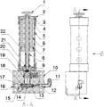
Fig. 1 is the structural representation of the utility model;
Fig. 2 is the 3 dimensional drawing of the utility model.
In the accompanying drawing, the list of parts of each label representative is following:
1, handle, 2, locking nut, 3, compress end cap, 4, the lucite tube inner bag, 5, the inner bag outer cover, 6, spring; 7, piston, 8, fuel sucking pipe, 9, the shutoff pin, 10, the valve piece, 11,90 degree are to the wire connection head, and 12, steel ball; 13, one-way valve, 14, plunger bushing, 15, shift fork, 16, interior hexagonal plug, 17, plunger, 18, piston spring; 19, output end cap external cover, 20, the lubricating cup pin, 21, O type circle fixture, 22, piston rod, 23, the consistent lubricant joint, 24, regulator.
Embodiment
Below in conjunction with accompanying drawing the principle and the characteristic of the utility model are described, institute gives an actual example and only is used to explain the utility model, is not the scope that is used to limit the utility model.
As shown in Figure 1; Lubricating cup is embedded in valve piece 10 inside; Be provided with output end cap external cover 19 between lubricating cup and the valve piece, hexagonal plug 16 and 90 degree were provided with shift fork 15, plunger 17 and one-way valve 13 to wire connection 11 successively in valve piece 10 left and right sides were equipped with respectively between interior hexagonal plug 16 and 90 is spent wire connection 11; Shift fork 15 lays respectively at the lubricating cup left and right sides with plunger 17, and plunger 17 outsides are connected with piston spring 18 and plunger bushing 14 in turn; Lubricating cup right side hollow cavity is built-in with steel ball 12, and top, lubricating cup top is connected with lubricating cup pin 20; Piston rod 22 and outside fuel sucking pipe 8, piston 7 and the piston 7 that connects thereof and compress the spring 6 that is equipped with between the end cap 3 and all place in the hollow cavity that lucite tube inner bag 4 forms; Piston rod 22 is connected through O type circle fixture 21 with fuel sucking pipe 8; Fuel sucking pipe 8 bottoms are connected with shutoff pin 9; Piston rod 22 tops are provided with handle 1, also are with inner bag overcoat 5 outside the lucite tube inner bag 4, compress end cap 3 and are connected by locking nut 2 with inner bag overcoat 5.
As shown in Figure 2, valve piece 10 outsides are equipped with regulator 24 and at least one consistent lubricant joint 23.
The utility model utilizes the invalid vibration that produces in the quartering hammer working procedure as power resources, and when quartering hammer was started working, the vibration of its generation made steel ball 12 in the oscillatory type lubricating grease automatic filling device along with the frequency of okperation of quartering hammer play up and down together.When steel ball 12 made progress play, steel ball 12 had been removed the pressure to shift fork 15, and owing to play, shift fork 15 also has the movement tendency that is upturned simultaneously.Because the pressure of 12 pairs of shift forks 15 of steel ball is removed, plunger 17 is motion backward under the effect of piston spring 18.Under vibration force and the acting in conjunction of plunger thrust, shift fork 15 rotates, and its front end is upturned.At this moment, because the motion of plunger 17, the filler opening at plunger bushing 14 middle parts just can be opened, and lubricating grease enters into the inner chamber of plunger bushing 14 through filler opening under the pressure effect of piston 7.When steel ball 12 down moved, steel ball 12 was pressed to the below with shift fork 15, and shift fork 15 just can promote plunger 17 forward.Plunger 17 is closed filler opening when travelling forward, and pushes the lubricating grease in the plunger bushing 14 to the place ahead simultaneously.Because plunger 17 motions are very fast; Plunger front end one-way valve 13 is closed in addition; In the enclosed cavity of plunger bushing 14, can produce instantaneous high pressure, when pressure surpassed the qualification pressure of one-way valve 13, one-way valve 13 just can be opened; Lubricant grease then is pushed in the oil inlet passage, through 90 degree wire connection 11 is acted on the quartering hammer.And then get into next work cycle.
The effect of the regulator 24 on the valve piece 10 is the injection amounts that are used for regulating lubricating grease in the quartering hammer, and consistent lubricant joint 23 is that device is used for the subsequent use joint of in quartering hammer grease up when damaging.After lubricating grease in the lubricating cup uses up; Except can directly passing through consistent lubricant joint 23 grease up in lubricating cup; Also can lubricating grease lubricating cup assembly be unloaded, utilize the Oil sucking device that himself is equipped with to come grease up in lubricating cup, specific operation process is: external cover 19 parts of the output end cap on the lubricating cup are immersed in the lubricating grease; The lubricating cup assembly top handle 1 of outwarding winding then; The push-and-pull piston rod 22 back and forth, and when upwards drawing piston rod 22, the shutoff pin of opening under the suction function in fuel sucking pipe 8 in the external cover 19 of output end cap 9 sucks lubricating grease in the oil pipe 8; When down promoting piston rod 22, O type circle fixture 21 can be pressed to the below with the lubricating grease in the fuel sucking pipe 8.At this moment, lubricating cup pin 20 is closed, and shutoff pin 9 will be opened, and lubricating grease just enters into lubricating cup smoothly.Continuous push-and-pull piston rod 7, lubricating grease will constantly get into, and spring 6 is constantly compressed, and is inhaled into up to lubricating grease and limits the position.And then lubricating grease lubricating cup assembly is screwed on the valve body assembly, shutoff this moment pin 9 is opened, and lubricating grease can enter into valve piece 10.
In addition,, on the valve piece, also set up oil mass adjustment screw, the output quantity of lubricating grease is controlled effectively for the friction position that makes quartering hammer obtains a desirable lubricants capacity.On the lubricating cup assembly, be provided with the oil mass peephole, just can observe what of lubricating grease amount in the lucite tube inner bag, when low on fuel, just can in time replenish through peephole.In addition, on lubricating cup inner bag outer cover, be provided with safe-guard line and caution notice, increased the safety in utilization and the functional reliability of oil filler.
The above is merely the preferred embodiment of the utility model, and is in order to restriction the utility model, not all within the spirit and principle of the utility model, any modification of being done, is equal to replacement, improvement etc., all should be included within the protection domain of the utility model.
Claims (8)
1. a lubricating grease automatic filling device is characterized in that, comprises valve body assembly and lubricating grease lubricating cup assembly; Wherein,
Said valve body assembly comprises valve piece and lubricating grease output mechanism, and said valve piece upper surface middle part has groove, and it is inner that said lubricating grease output mechanism is installed on said valve piece;
Said lubricating grease lubricating cup assembly comprises that lubricating cup and negative pressure provide mechanism, and said negative pressure provides mechanism to be fixed on the said valve piece, and said lubricating cup places in the groove of said valve piece.
2. lubricating grease automatic filling device according to claim 1 is characterized in that, the said lubricating cup outside is with out the external cover of end cap, and said lubricating cup top is connected with the lubricating cup pin.
3. lubricating grease automatic filling device according to claim 1 is characterized in that, the said valve piece left and right sides is connected with plug respectively and to the wire connection head, said valve piece is externally connected to consistent lubricant joint and the regulator of regulating the lubricating grease injection amount.
4. lubricating grease automatic filling device according to claim 3 is characterized in that, said plug is interior hexagonal plug, said joint be 90 the degree to the wire connection head, said consistent lubricant joint is at least one.
5. lubricating grease automatic filling device according to claim 1 and 2 is characterized in that, said lubricating grease output mechanism comprises steel ball, one-way valve, plunger and shift fork, and said steel ball places in the hollow cavity on said lubricating cup right side; Said plunger places said lubricating cup below, and its right ends connects said shift fork and one-way valve respectively; Said shift fork and one-way valve are positioned at said lubricating cup both sides.
6. lubricating grease automatic filling device according to claim 5 is characterized in that, said plunger outside is connected with piston spring and plunger bushing in turn.
7. lubricating grease automatic filling device according to claim 1; It is characterized in that; Said negative pressure provides mechanism to comprise piston rod, fuel sucking pipe, piston, spring, lucite tube inner bag and compresses end cap, and said piston rod, fuel sucking pipe, piston, spring are located in the hollow cavity of lucite tube inner bag formation, and said lucite tube inner bag top is connected with and compresses end cap; Said piston rod outside is connected with fuel sucking pipe and piston in turn, and said spring is located at said piston and compresses between the end cap.
8. lubricating grease automatic filling device according to claim 7; It is characterized in that said piston rod is connected through O type circle fixture with fuel sucking pipe, said fuel sucking pipe bottom is connected with the shutoff pin; Said piston rod top is provided with handle, and said lucite tube inner bag also is with the inner bag overcoat outward.
Priority Applications (1)
| Application Number | Priority Date | Filing Date | Title |
|---|---|---|---|
| CN2012202371534U CN202629541U (en) | 2012-05-24 | 2012-05-24 | Automatic lubricating grease injecting device |
Applications Claiming Priority (1)
| Application Number | Priority Date | Filing Date | Title |
|---|---|---|---|
| CN2012202371534U CN202629541U (en) | 2012-05-24 | 2012-05-24 | Automatic lubricating grease injecting device |
Publications (1)
| Publication Number | Publication Date |
|---|---|
| CN202629541U true CN202629541U (en) | 2012-12-26 |
Family
ID=47382739
Family Applications (1)
| Application Number | Title | Priority Date | Filing Date |
|---|---|---|---|
| CN2012202371534U Expired - Lifetime CN202629541U (en) | 2012-05-24 | 2012-05-24 | Automatic lubricating grease injecting device |
Country Status (1)
| Country | Link |
|---|---|
| CN (1) | CN202629541U (en) |
Cited By (2)
| Publication number | Priority date | Publication date | Assignee | Title |
|---|---|---|---|---|
| CN106030183A (en) * | 2014-03-07 | 2016-10-12 | Klt株式会社 | Lubricant injector |
| CN112177087A (en) * | 2020-10-28 | 2021-01-05 | 安徽丰进机械有限公司 | Piston guide structure for hydraulic breaking hammer and working method |
-
2012
- 2012-05-24 CN CN2012202371534U patent/CN202629541U/en not_active Expired - Lifetime
Cited By (2)
| Publication number | Priority date | Publication date | Assignee | Title |
|---|---|---|---|---|
| CN106030183A (en) * | 2014-03-07 | 2016-10-12 | Klt株式会社 | Lubricant injector |
| CN112177087A (en) * | 2020-10-28 | 2021-01-05 | 安徽丰进机械有限公司 | Piston guide structure for hydraulic breaking hammer and working method |
Similar Documents
| Publication | Publication Date | Title |
|---|---|---|
| CN202629541U (en) | Automatic lubricating grease injecting device | |
| CN207648428U (en) | A kind of novel pneumatic fixed-quantity oiling machine | |
| CN207120766U (en) | Sleeper bolt double end oiling spanner | |
| CN204629050U (en) | The long-term automatic filling device of a kind of long-range lubricating grease | |
| CN216350731U (en) | Grout cup pressure relief device | |
| CN104633424A (en) | Remote lubricating grease long-term filling device and filling method thereof | |
| CN202040313U (en) | Automatic lubricating device of ingot casting machine chain | |
| CN201103782Y (en) | Automatic oil transfer device | |
| CN203488952U (en) | Pneumatic type lubricating grease injection device | |
| CN210219257U (en) | Long-acting automatic lubricating device for central shaft and tail shaft of oil pumping unit | |
| CN203363616U (en) | Portable electric consistent grease machine | |
| CN209991192U (en) | Sealing connecting piece of disposable straight barrel type grease barrel | |
| CN113606481A (en) | Lubricating oil adding device for motor part production | |
| CN104141872A (en) | Lubricating oil injector capable of heating oil | |
| CN211976496U (en) | Oil ejector | |
| CN111379959A (en) | Automatic lubricating device for sliding part of die-casting die | |
| CN203297908U (en) | Bidirectional plunger lubricating oil pump | |
| CN204754850U (en) | Sucker rod socket in oil pipe | |
| CN204954723U (en) | Hydraulic wrench | |
| CN203823402U (en) | Grease gun capable of continuously filling grease | |
| CN211716213U (en) | Electric grease gun | |
| CN103277654A (en) | Novel grease gun head | |
| CN220130902U (en) | Lubricating oil storage tank | |
| CN201391730Y (en) | Lubricating grease slow filling device | |
| CN208817054U (en) | A kind of pivoting support production care device that oils |
Legal Events
| Date | Code | Title | Description |
|---|---|---|---|
| C14 | Grant of patent or utility model | ||
| GR01 | Patent grant | ||
| CX01 | Expiry of patent term | ||
| CX01 | Expiry of patent term |
Granted publication date: 20121226 |