CN202628362U - Water heater of engine - Google Patents
Water heater of engine Download PDFInfo
- Publication number
- CN202628362U CN202628362U CN201220348616.4U CN201220348616U CN202628362U CN 202628362 U CN202628362 U CN 202628362U CN 201220348616 U CN201220348616 U CN 201220348616U CN 202628362 U CN202628362 U CN 202628362U
- Authority
- CN
- China
- Prior art keywords
- water
- temperature control
- heating
- temperature
- housing
- Prior art date
- Legal status (The legal status is an assumption and is not a legal conclusion. Google has not performed a legal analysis and makes no representation as to the accuracy of the status listed.)
- Expired - Fee Related
Links
- XLYOFNOQVPJJNP-UHFFFAOYSA-N water Substances O XLYOFNOQVPJJNP-UHFFFAOYSA-N 0.000 title claims abstract description 36
- 238000010438 heat treatment Methods 0.000 claims abstract description 30
- 238000013021 overheating Methods 0.000 abstract description 4
- 230000007423 decrease Effects 0.000 abstract description 3
- 238000010586 diagram Methods 0.000 description 3
- 238000007789 sealing Methods 0.000 description 3
- 239000000314 lubricant Substances 0.000 description 2
- VYPSYNLAJGMNEJ-UHFFFAOYSA-N Silicium dioxide Chemical compound O=[Si]=O VYPSYNLAJGMNEJ-UHFFFAOYSA-N 0.000 description 1
- 238000005054 agglomeration Methods 0.000 description 1
- 230000002776 aggregation Effects 0.000 description 1
- 230000009286 beneficial effect Effects 0.000 description 1
- 238000009835 boiling Methods 0.000 description 1
- 230000007812 deficiency Effects 0.000 description 1
- 238000009434 installation Methods 0.000 description 1
- 230000001050 lubricating effect Effects 0.000 description 1
- 238000000034 method Methods 0.000 description 1
- 238000004064 recycling Methods 0.000 description 1
- 239000000741 silica gel Substances 0.000 description 1
- 229910002027 silica gel Inorganic materials 0.000 description 1
- 229920002379 silicone rubber Polymers 0.000 description 1
- 239000004945 silicone rubber Substances 0.000 description 1
Images


Classifications
-
- Y—GENERAL TAGGING OF NEW TECHNOLOGICAL DEVELOPMENTS; GENERAL TAGGING OF CROSS-SECTIONAL TECHNOLOGIES SPANNING OVER SEVERAL SECTIONS OF THE IPC; TECHNICAL SUBJECTS COVERED BY FORMER USPC CROSS-REFERENCE ART COLLECTIONS [XRACs] AND DIGESTS
- Y02—TECHNOLOGIES OR APPLICATIONS FOR MITIGATION OR ADAPTATION AGAINST CLIMATE CHANGE
- Y02T—CLIMATE CHANGE MITIGATION TECHNOLOGIES RELATED TO TRANSPORTATION
- Y02T10/00—Road transport of goods or passengers
- Y02T10/10—Internal combustion engine [ICE] based vehicles
- Y02T10/12—Improving ICE efficiencies
Landscapes
- Air-Conditioning For Vehicles (AREA)
Abstract
本实用新型涉及一种发动机水加热器,包括壳体、进水口、出水口,壳体从侧面看为一个近似直角三角形,壳体较小的一端设有进水口,出水口设置在壳体较大的一端的侧面,其中壳体内部为加热腔,所述加热腔里面设置有加热管和过热保护装置,过热保护装置的指示灯位于电路板上,电路板固定在壳体后盖的内侧壁上。所述过热保护装置包括两个温控开关,其中一个温控开关控制水的温度,另一个温控开关用作过热保护。本实用新型在加热电路中串联两个温控开关,分别对水的温度和干烧进行控制,一个温控开关把水温控制在40度,温度升高自动断电,这样还能节约能源,另一个温控开关对干烧进行控制,当水量变少的时候容易产生干烧损坏加热器,加入干烧温控开关可以延长加热器的使用寿命。
The utility model relates to an engine water heater, which comprises a casing, a water inlet and a water outlet. The casing is an approximately right-angled triangle viewed from the side, and the smaller end of the casing is provided with a water inlet. The side of the large end, wherein the inside of the housing is a heating chamber, the heating chamber is provided with a heating tube and an overheating protection device, the indicator light of the overheating protection device is located on the circuit board, and the circuit board is fixed on the inner side wall of the rear cover of the housing superior. The overheat protection device includes two temperature control switches, one temperature control switch controls the temperature of water, and the other temperature control switch is used for overheat protection. In the utility model, two temperature control switches are connected in series in the heating circuit to control the water temperature and dry heating respectively. One temperature control switch controls the water temperature at 40 degrees, and the power is automatically cut off when the temperature rises, which can also save energy. A temperature control switch controls dry heating. When the water volume decreases, it is easy to cause dry heating and damage the heater. Adding a dry heating temperature control switch can prolong the service life of the heater.
Description
技术领域 technical field
本实用新型涉及发动机辅助加热领域,具体设计一种发动机水加热器。 The utility model relates to the field of engine auxiliary heating, and specifically designs an engine water heater.
背景技术 Background technique
随着社会的发展,发动机作为一种提供动力的设备应用越来越广泛,除了我们熟悉的应用在汽车上发动机外,发电机组也是依靠发动机来提供动力。 With the development of society, the engine is used more and more widely as a power-providing device. In addition to the engine that we are familiar with, the generator set also relies on the engine to provide power.
发动机在冬天使用的时候因为冷启动的时候,润滑剂会结块,发动机不好启动,同时因为润滑剂结块润滑效果下降,对发动机发动会造成比较大的损害,缩短发动机的使用寿命,所以对发动机的加热装置成为发动机必不可少的辅机。专利ZL00253119.4提出了一种发动机加热器,但是该专利没有解决温度持续增高和干烧这个问题。 When the engine is used in winter, the lubricant will agglomerate during cold start, and the engine will not start well. At the same time, the lubricating effect of the lubricant agglomeration will decrease, which will cause relatively large damage to the engine and shorten the service life of the engine. The heating device for the engine becomes an indispensable auxiliary machine for the engine. Patent ZL00253119.4 proposes a kind of engine heater, but this patent does not solve this problem that temperature keeps increasing and dry burning.
发明内容 Contents of the invention
本实用新型针对现有技术存在的不足,提出一种发动机水加热器。 The utility model proposes an engine water heater aiming at the deficiencies in the prior art.
本实用新型的技术方案是:一种发动机水加热器,包括壳体、进水口、出水口,壳体从侧面看为一个近似直角三角形,壳体较小的一端设有进水口,出水口设置在壳体较大的一端的侧面,其中壳体内部为加热腔,所述加热腔里面设置有加热管和过热保护装置,过热保护装置的指示灯位于电路板上,电路板固定在壳体后盖的内侧壁上。 The technical scheme of the utility model is: an engine water heater, including a housing, a water inlet, and a water outlet. The housing is viewed from the side as an approximately right-angled triangle, and the smaller end of the housing is provided with a water inlet and a water outlet. On the side of the larger end of the shell, the inside of the shell is a heating chamber, and a heating tube and an overheating protection device are arranged inside the heating chamber. The indicator light of the overheating protection device is located on the circuit board, and the circuit board is fixed behind the shell on the inside wall of the cover.
所述的发动机水加热器,所述过热保护装置包括两个温控开关,其中一个温控开关控制水的温度,另一个温控开关用作过热保护。 In the engine water heater, the overheat protection device includes two temperature control switches, one of which controls the temperature of the water, and the other temperature control switch is used for overheat protection.
本实用新型的有益效果是: The beneficial effects of the utility model are:
1.本实用新型在加热电路中串联两个温控开关,分别对水的温度和干烧进行控制,一个温控开关把水温控制在40度,温度升高自动断电,这样还能节约能源,另一个温控开关对干烧进行控制,当水量变少的时候容易产生干烧损坏加热器,加入干烧温控开关可以延长加热器的使用寿命。 1. In the utility model, two temperature control switches are connected in series in the heating circuit to control the water temperature and dry heating respectively. One temperature control switch controls the water temperature at 40 degrees, and the power is automatically cut off when the temperature rises, which can also save energy. , another temperature control switch controls dry heating. When the water volume decreases, it is easy to cause dry heating and damage the heater. Adding a dry heating temperature control switch can prolong the service life of the heater.
2.本实用新型的外壳上设置有指示灯,可以方便的观察到加热器的工作状态,方便工作人员检查。 2. The housing of the utility model is provided with an indicator light, which can conveniently observe the working state of the heater, and is convenient for the staff to check.
附图说明 Description of drawings
图1为本实用新型工作流程示意框图; Fig. 1 is a schematic block diagram of the utility model workflow;
图2为本实用新型的组装结构示意图; Fig. 2 is the assembly structure schematic diagram of the present utility model;
图3为本实用新型的电路工作示意图; Fig. 3 is the schematic diagram of circuit work of the present utility model;
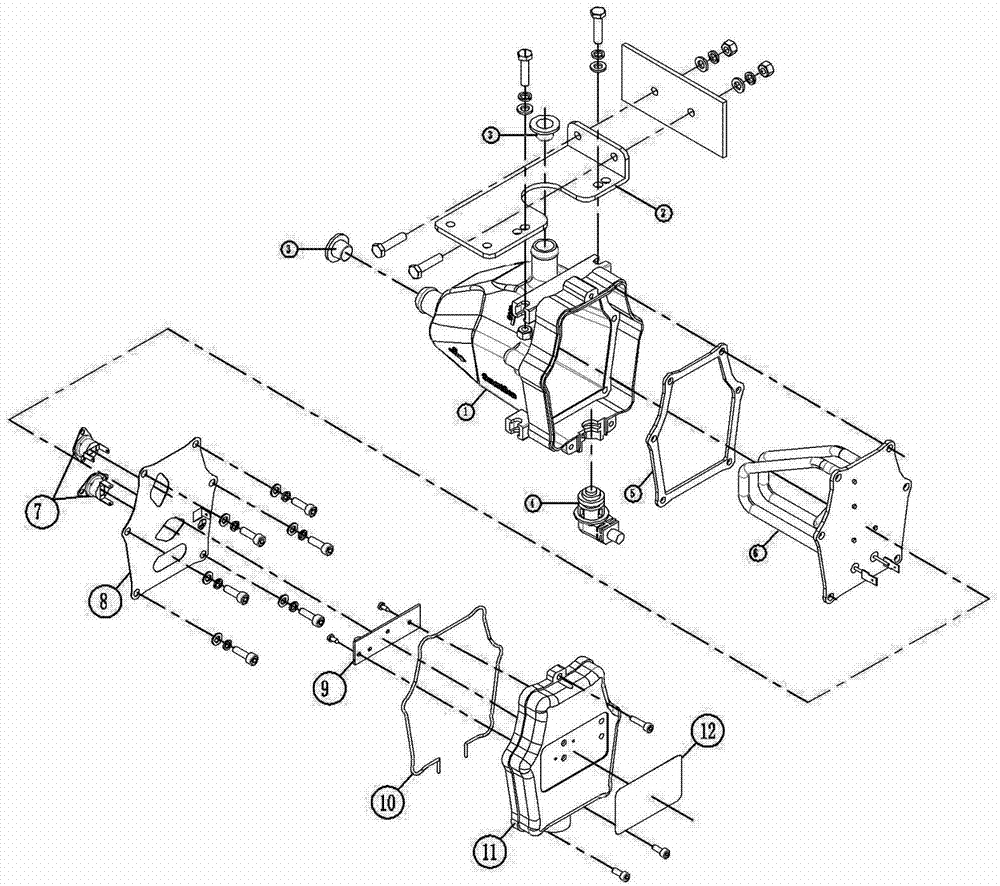
图中:1为加热器壳体,2为支架,3为管堵,4为线缆,5为密封圈,6为加热管,7为温控开关,8为安装版,9为电路板,10为发泡硅胶密封条,11为外壳后盖,12为面板,K1、K2为温控开关。 In the figure: 1 is the heater shell, 2 is the bracket, 3 is the pipe plug, 4 is the cable, 5 is the sealing ring, 6 is the heating tube, 7 is the temperature control switch, 8 is the installation plate, 9 is the circuit board, 10 is a foamed silica gel sealing strip, 11 is a casing back cover, 12 is a panel, and K1 and K2 are temperature control switches.
具体实施方式 Detailed ways
实施例1:一种发动机水加热器,包括壳体、壳体从侧面看为一个近似直角三角形,在壳体的最小端开设一个进水口,出水口设置在壳体较大一端的顶部,壳体内部为加热腔,壳体的大端安装有加热管,加热管法兰座和壳体之间垫有硅橡胶密封圈,防止水泄露,在加热管两个接线柱中的一个接线柱上串联两个温控开关,其中一个温控开关负责限制水温在40度以下,另一温控开关防止干烧。其中2个温控开关与加热管串联连接,温控开关被安装板固定在加热管法兰座上,线路板固定在加热器后壳,安装板的外侧为壳体后盖,壳体后盖通过螺丝和壳体固接。 Embodiment 1: A water heater for an engine, comprising a housing, the housing is an approximately right-angled triangle viewed from the side, a water inlet is provided at the smallest end of the housing, and the water outlet is arranged on the top of the larger end of the housing. The inside of the body is a heating chamber, and the large end of the shell is equipped with a heating tube. A silicone rubber sealing ring is placed between the flange seat of the heating tube and the shell to prevent water leakage. On one of the two terminals of the heating tube Two temperature control switches are connected in series, one temperature control switch is responsible for limiting the water temperature below 40 degrees, and the other temperature control switch prevents dry boiling. Two of the temperature control switches are connected in series with the heating tube, the temperature control switch is fixed on the flange seat of the heating tube by the mounting plate, the circuit board is fixed on the rear shell of the heater, the outer side of the mounting plate is the rear cover of the housing, and the rear cover of the housing Fastened to the shell by screws.
所述电路板上安装有两个发光二极管指示灯,其中一个发光二极管和整流二极管、电阻先串联,再和发热管并联,并联后再串联两个温控开关,构成回路。另一个发光二极管先和电阻、整流二极管串联构成回路。在加热器后盖上留有指示灯导光孔,小孔和电路板上发光二极管的位置匹配,在壳体后盖上还装有半透明圆孔的面膜,用来观察指示灯的状态。 Two light-emitting diode indicator lights are installed on the circuit board, one of which is first connected in series with the rectifier diode and the resistor, and then connected in parallel with the heating tube, and then connected in parallel and then connected in series with two temperature control switches to form a loop. Another light-emitting diode is first connected in series with a resistor and a rectifier diode to form a loop. There is a light guide hole for the indicator light on the back cover of the heater, and the small hole matches the position of the light-emitting diode on the circuit board. There is also a mask with translucent round holes on the back cover of the shell to observe the status of the indicator light.
加热器工作原理:启动加热器,冷水受热后上升,加热过的水进入发动机水道,并对发动机进行预热,之后水再流回加热器进行加热,循环利用。 The working principle of the heater: start the heater, the cold water rises after being heated, the heated water enters the engine waterway, and preheats the engine, and then the water flows back to the heater for heating and recycling.
Claims (2)
Priority Applications (1)
| Application Number | Priority Date | Filing Date | Title |
|---|---|---|---|
| CN201220348616.4U CN202628362U (en) | 2012-07-18 | 2012-07-18 | Water heater of engine |
Applications Claiming Priority (1)
| Application Number | Priority Date | Filing Date | Title |
|---|---|---|---|
| CN201220348616.4U CN202628362U (en) | 2012-07-18 | 2012-07-18 | Water heater of engine |
Publications (1)
| Publication Number | Publication Date |
|---|---|
| CN202628362U true CN202628362U (en) | 2012-12-26 |
Family
ID=47381569
Family Applications (1)
| Application Number | Title | Priority Date | Filing Date |
|---|---|---|---|
| CN201220348616.4U Expired - Fee Related CN202628362U (en) | 2012-07-18 | 2012-07-18 | Water heater of engine |
Country Status (1)
| Country | Link |
|---|---|
| CN (1) | CN202628362U (en) |
-
2012
- 2012-07-18 CN CN201220348616.4U patent/CN202628362U/en not_active Expired - Fee Related
Similar Documents
| Publication | Publication Date | Title |
|---|---|---|
| CN104406201A (en) | Self-generating gas cooker | |
| CN203642453U (en) | Self-powered gas water heater | |
| CN206905266U (en) | A kind of luminous energy DC potential hydrophone | |
| CN202628362U (en) | Water heater of engine | |
| CN201909444U (en) | Electromagnetic heating oil boiler | |
| CN205305322U (en) | Fill electric pile liquid cooling electronic heat sink and fill electric pile | |
| CN205030036U (en) | Novel converter heat dissipation device | |
| CN204596921U (en) | A kind of battery of electric vehicle | |
| CN206018343U (en) | A kind of LED illumination device with radiator fan | |
| CN204812955U (en) | Take safety device's plumbing mattress host computer | |
| CN205279203U (en) | Multifunctional range hood | |
| CN202851232U (en) | Forced water circulating and water preheating device of diesel generator | |
| CN103644011A (en) | Oil pan provided with heating device | |
| CN201937846U (en) | Universal intelligent heating device for self-service equipment | |
| CN203024013U (en) | Energy conservation light-emitting diode (LED) auto head lamp | |
| CN201242290Y (en) | Control circuit for electric fireplace heater | |
| CN102631141B (en) | Electric oven | |
| CN201757387U (en) | High-power LED lamp forced air-cooled heat dissipation structure | |
| CN206251558U (en) | A kind of constant temperature regulator cubicle | |
| CN103640492B (en) | The method of low-temperature protection system device of power battery of electric vehicle | |
| CN205939722U (en) | Multi -functional water heater with timing function | |
| CN204494840U (en) | Air transmitted heating type water heater | |
| CN202555430U (en) | Shower head device with functions of water flow generation and temperature display | |
| CN204827636U (en) | Car and engine, engine cooling system, engine water pump thereof | |
| CN213302874U (en) | A high-protection oil pump controller with good heat dissipation effect |
Legal Events
| Date | Code | Title | Description |
|---|---|---|---|
| C14 | Grant of patent or utility model | ||
| GR01 | Patent grant | ||
| CF01 | Termination of patent right due to non-payment of annual fee |
Granted publication date: 20121226 Termination date: 20150718 |
|
| EXPY | Termination of patent right or utility model |