CN202607404U - Reference guide rail vertical face tight-fitting and close-attaching device - Google Patents
Reference guide rail vertical face tight-fitting and close-attaching device Download PDFInfo
- Publication number
- CN202607404U CN202607404U CN 201120478188 CN201120478188U CN202607404U CN 202607404 U CN202607404 U CN 202607404U CN 201120478188 CN201120478188 CN 201120478188 CN 201120478188 U CN201120478188 U CN 201120478188U CN 202607404 U CN202607404 U CN 202607404U
- Authority
- CN
- China
- Prior art keywords
- guide rail
- cam
- grind
- fitting
- vertical face
- Prior art date
- Legal status (The legal status is an assumption and is not a legal conclusion. Google has not performed a legal analysis and makes no representation as to the accuracy of the status listed.)
- Expired - Fee Related
Links
Images
Abstract
A reference guide rail vertical face tight-fitting and close-attaching device belongs to the numerical control machine tool field. A cam seat is arranged inside a screw rod seat. The screw rod seat is connected with an adjusting screw. A fixed plate is mounted on the bottom of a tightly-fitted slide base. A cam is close to a non-reference guide rail vertical face. The tightly fitted slide base is contacted with a tight-fitting guide rail face. By tightening up the adjusting screw, the tightly-fitted slide base can be moved and closely attached to the tight-fitting guide rail face. The beneficial effects of the reference guide rail vertical face tight-fitting and close-attaching device are that the slide base not only can be closely attached to the guide rail vertical face, but also can be repeatedly moved in a front and back manner through the rolling of the cam to realize the tight-fitting of the reference guide rail vertical face, so that the producing and processing precision of machine tools can be guaranteed.
Description
Technical field
The utility model relates to the basic rack facade and closes to grind and be adjacent to device, belongs to the Digit Control Machine Tool field.
Background technology
Along with industrial expansion, the automaticity in the machining industry is increasingly high, and Digit Control Machine Tool obtains increasing application.In process; The feed system of Digit Control Machine Tool often is in automatic break-in state, and when the direction of feed of lathe changed, the travelling gear side clearance can cause command pulse to lose; Thereby and produce reverse dead band and influence machining accuracy, the gap that therefore something must be done to when eliminating gear drive.
Summary of the invention
In view of the defective that prior art exists, the purpose of the utility model provides a kind of basic rack facade simple in structure, quick detachable, that do not damage guide rail and closes to grind and be adjacent to device.
For realizing above-mentioned purpose, the technical solution that the utility model adopted mainly is: the basic rack facade closes to grind and is adjacent to device, it is characterized in that: cam chair is built in the screw bolt seat; Screw bolt seat connects the adjustment screw rod; Fixed head is installed in and is closed the bottom surface of grinding slide, and cam is pressed close to non-basic rack facade, is closed to grind slide and grind guide pass and contact with closing; Through tightening the adjustment screw rod, make by the lapping-in slide and move and grind guide pass and be adjacent to closing.
Said cam is selected the brass material for use.
The bar portion of said cam chair can slide.
Can be adjacent to rolling at the guide rail facade through cam by the lapping-in slide.
The basic rack facade closes to grind and is adjacent to device, and its beneficial effect is: slide not only is adjacent to the guide rail facade, can also roll through cam, repeats to seesaw, and can realize that closing of basic rack facade grind, and guarantees the production and processing precision of lathe.
Description of drawings
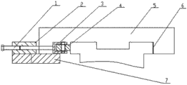
Fig. 1 is that the basic rack facade closes and grinds the structure diagram that is adjacent to device.
Fig. 1 Reference numeral is following: 1, adjustment screw rod, 2, screw bolt seat, 3, cam chair, 4, cam, 5, closed and grind slide, 6, close and grind guide pass, 7, fixed head.
The specific embodiment
According to Fig. 1 the basic rack facade is closed to grind below and be adjacent to device and further specify: cam 4 is selected brass material for use; Cam chair 3 is built in the screw bolt seat 2, and the bar portion of cam chair can slide, and cam chair 3 is built in the screw bolt seat 2; Screw bolt seat 2 connects adjustment screw rod 1; Fixed head 7 is installed in and is closed the bottom surface of grinding slide 5, and cam 4 is pressed close to non-basic rack facade, is closed to grind slide 5 and grind guide pass 6 and contact with closing; Through tightening adjustment screw rod 1, make by lapping-in slide 5 and move and grind guide pass 6 and be adjacent to closing.
Claims (4)
1. the basic rack facade closes to grind and is adjacent to device; It is characterized in that: cam chair (3) is built in the screw bolt seat (2), and screw bolt seat (2) connects adjustment screw rod (1), and fixed head (7) is installed in and is closed the bottom surface of grinding slide (5); Cam (4) is pressed close to non-basic rack facade; Closed and grind slide (5) and grind guide pass (6) and contact with closing,, made mobile and follow to close and grind guide pass (6) and be adjacent to by lapping-in slide (5) through tightening adjustment screw rod (1).
2. basic rack facade according to claim 1 closes to grind and is adjacent to device, it is characterized in that: said cam (4) is selected the brass material for use.
3. basic rack facade according to claim 1 closes to grind and is adjacent to device, it is characterized in that: the bar portion of said cam chair (3) can slide.
4. basic rack facade according to claim 1 closes to grind and is adjacent to device, it is characterized in that: can be adjacent to rolling at the guide rail facade through cam (4) by lapping-in slide (5).
Priority Applications (1)
| Application Number | Priority Date | Filing Date | Title |
|---|---|---|---|
| CN 201120478188 CN202607404U (en) | 2011-11-28 | 2011-11-28 | Reference guide rail vertical face tight-fitting and close-attaching device |
Applications Claiming Priority (1)
| Application Number | Priority Date | Filing Date | Title |
|---|---|---|---|
| CN 201120478188 CN202607404U (en) | 2011-11-28 | 2011-11-28 | Reference guide rail vertical face tight-fitting and close-attaching device |
Publications (1)
| Publication Number | Publication Date |
|---|---|
| CN202607404U true CN202607404U (en) | 2012-12-19 |
Family
ID=47341136
Family Applications (1)
| Application Number | Title | Priority Date | Filing Date |
|---|---|---|---|
| CN 201120478188 Expired - Fee Related CN202607404U (en) | 2011-11-28 | 2011-11-28 | Reference guide rail vertical face tight-fitting and close-attaching device |
Country Status (1)
| Country | Link |
|---|---|
| CN (1) | CN202607404U (en) |
Cited By (2)
| Publication number | Priority date | Publication date | Assignee | Title |
|---|---|---|---|---|
| CN103692224A (en) * | 2013-12-06 | 2014-04-02 | 常州金安冶金设备有限公司 | Hydrostatic guide rail |
| CN109514385A (en) * | 2019-01-03 | 2019-03-26 | 天润曲轴股份有限公司 | Rectangular guideway grinds an auxiliary device |
-
2011
- 2011-11-28 CN CN 201120478188 patent/CN202607404U/en not_active Expired - Fee Related
Cited By (3)
| Publication number | Priority date | Publication date | Assignee | Title |
|---|---|---|---|---|
| CN103692224A (en) * | 2013-12-06 | 2014-04-02 | 常州金安冶金设备有限公司 | Hydrostatic guide rail |
| CN109514385A (en) * | 2019-01-03 | 2019-03-26 | 天润曲轴股份有限公司 | Rectangular guideway grinds an auxiliary device |
| CN109514385B (en) * | 2019-01-03 | 2023-10-31 | 天润工业技术股份有限公司 | Auxiliary device for grinding points of rectangular guide rail |
Similar Documents
| Publication | Publication Date | Title |
|---|---|---|
| CN202862003U (en) | Thread grinding wheel dressing device | |
| CN202984708U (en) | Boring cutter adjusting device | |
| CN203679297U (en) | Fine-adjustment tool holder | |
| CN202655955U (en) | Clamping device | |
| CN202607404U (en) | Reference guide rail vertical face tight-fitting and close-attaching device | |
| CN102166791B (en) | Silicon rod multi-wire cutting machine guide wheel slotting one-time molding combined machine tool and application thereof | |
| CN205350068U (en) | Cross roller slide bracket | |
| CN203610744U (en) | Small-sized curve copying milling machine | |
| CN204935102U (en) | A kind of column of adjustable angle | |
| CN203918777U (en) | Dovetail guide clamp | |
| CN203944893U (en) | A kind of banked direction control valves Special two-side milling machine | |
| CN202499544U (en) | Automatic feeding positioning mechanism | |
| CN203679954U (en) | Paralleled surface grinding machine | |
| CN202753000U (en) | Large-blade random location pressing and damping device | |
| CN202087849U (en) | Mechanical fine-tuning tool apron | |
| CN203557547U (en) | Mobile column base and column cap cutter | |
| CN203495747U (en) | Grinding head adjusting device | |
| CN203003493U (en) | Machine tool spindle box ram structure | |
| CN202388298U (en) | Transmission device | |
| CN202412781U (en) | Device for finely tuning gaps of air tracks for press machines | |
| CN203665079U (en) | Vertical type CNC boring and milling machine | |
| CN203778891U (en) | Rapid reloading numerical control milling machine for milling rack tooth form | |
| CN203380617U (en) | Numerical control machine tool with lead screw convenient to mount | |
| CN103447946A (en) | Grinding head adjusting device | |
| CN203792045U (en) | Fast clamping mechanism for large-size thin-plate parts |
Legal Events
| Date | Code | Title | Description |
|---|---|---|---|
| C14 | Grant of patent or utility model | ||
| GR01 | Patent grant | ||
| CF01 | Termination of patent right due to non-payment of annual fee |
Granted publication date: 20121219 Termination date: 20141128 |
|
| EXPY | Termination of patent right or utility model |