CN202545587U - External guiding solid cage of aligning roller bearing for vibrating machine - Google Patents
External guiding solid cage of aligning roller bearing for vibrating machine Download PDFInfo
- Publication number
- CN202545587U CN202545587U CN2012200407495U CN201220040749U CN202545587U CN 202545587 U CN202545587 U CN 202545587U CN 2012200407495 U CN2012200407495 U CN 2012200407495U CN 201220040749 U CN201220040749 U CN 201220040749U CN 202545587 U CN202545587 U CN 202545587U
- Authority
- CN
- China
- Prior art keywords
- guiding
- cages
- solid
- roller bearing
- cage
- Prior art date
- Legal status (The legal status is an assumption and is not a legal conclusion. Google has not performed a legal analysis and makes no representation as to the accuracy of the status listed.)
- Expired - Fee Related
Links
- 239000007787 solid Substances 0.000 title claims abstract description 47
- 230000000694 effects Effects 0.000 claims description 3
- 238000005461 lubrication Methods 0.000 claims description 3
- 230000001133 acceleration Effects 0.000 abstract description 8
- 230000002035 prolonged effect Effects 0.000 abstract description 3
- 238000000034 method Methods 0.000 description 2
- 238000005516 engineering process Methods 0.000 description 1
- 238000005096 rolling process Methods 0.000 description 1
Images


Classifications
-
- F—MECHANICAL ENGINEERING; LIGHTING; HEATING; WEAPONS; BLASTING
- F16—ENGINEERING ELEMENTS AND UNITS; GENERAL MEASURES FOR PRODUCING AND MAINTAINING EFFECTIVE FUNCTIONING OF MACHINES OR INSTALLATIONS; THERMAL INSULATION IN GENERAL
- F16C—SHAFTS; FLEXIBLE SHAFTS; ELEMENTS OR CRANKSHAFT MECHANISMS; ROTARY BODIES OTHER THAN GEARING ELEMENTS; BEARINGS
- F16C33/00—Parts of bearings; Special methods for making bearings or parts thereof
- F16C33/30—Parts of ball or roller bearings
- F16C33/46—Cages for rollers or needles
- F16C33/48—Cages for rollers or needles for multiple rows of rollers or needles
- F16C33/485—Cages for rollers or needles for multiple rows of rollers or needles with two or more juxtaposed cages joined together or interacting with each other
-
- F—MECHANICAL ENGINEERING; LIGHTING; HEATING; WEAPONS; BLASTING
- F16—ENGINEERING ELEMENTS AND UNITS; GENERAL MEASURES FOR PRODUCING AND MAINTAINING EFFECTIVE FUNCTIONING OF MACHINES OR INSTALLATIONS; THERMAL INSULATION IN GENERAL
- F16C—SHAFTS; FLEXIBLE SHAFTS; ELEMENTS OR CRANKSHAFT MECHANISMS; ROTARY BODIES OTHER THAN GEARING ELEMENTS; BEARINGS
- F16C33/00—Parts of bearings; Special methods for making bearings or parts thereof
- F16C33/30—Parts of ball or roller bearings
- F16C33/46—Cages for rollers or needles
- F16C33/49—Cages for rollers or needles comb-shaped
- F16C33/494—Massive or moulded comb cages
- F16C33/495—Massive or moulded comb cages formed as one piece cages, i.e. monoblock comb cages
-
- F—MECHANICAL ENGINEERING; LIGHTING; HEATING; WEAPONS; BLASTING
- F16—ENGINEERING ELEMENTS AND UNITS; GENERAL MEASURES FOR PRODUCING AND MAINTAINING EFFECTIVE FUNCTIONING OF MACHINES OR INSTALLATIONS; THERMAL INSULATION IN GENERAL
- F16C—SHAFTS; FLEXIBLE SHAFTS; ELEMENTS OR CRANKSHAFT MECHANISMS; ROTARY BODIES OTHER THAN GEARING ELEMENTS; BEARINGS
- F16C33/00—Parts of bearings; Special methods for making bearings or parts thereof
- F16C33/30—Parts of ball or roller bearings
- F16C33/66—Special parts or details in view of lubrication
- F16C33/6637—Special parts or details in view of lubrication with liquid lubricant
- F16C33/6681—Details of distribution or circulation inside the bearing, e.g. grooves on the cage or passages in the rolling elements
-
- F—MECHANICAL ENGINEERING; LIGHTING; HEATING; WEAPONS; BLASTING
- F16—ENGINEERING ELEMENTS AND UNITS; GENERAL MEASURES FOR PRODUCING AND MAINTAINING EFFECTIVE FUNCTIONING OF MACHINES OR INSTALLATIONS; THERMAL INSULATION IN GENERAL
- F16C—SHAFTS; FLEXIBLE SHAFTS; ELEMENTS OR CRANKSHAFT MECHANISMS; ROTARY BODIES OTHER THAN GEARING ELEMENTS; BEARINGS
- F16C19/00—Bearings with rolling contact, for exclusively rotary movement
- F16C19/22—Bearings with rolling contact, for exclusively rotary movement with bearing rollers essentially of the same size in one or more circular rows, e.g. needle bearings
- F16C19/34—Bearings with rolling contact, for exclusively rotary movement with bearing rollers essentially of the same size in one or more circular rows, e.g. needle bearings for both radial and axial load
- F16C19/38—Bearings with rolling contact, for exclusively rotary movement with bearing rollers essentially of the same size in one or more circular rows, e.g. needle bearings for both radial and axial load with two or more rows of rollers
-
- F—MECHANICAL ENGINEERING; LIGHTING; HEATING; WEAPONS; BLASTING
- F16—ENGINEERING ELEMENTS AND UNITS; GENERAL MEASURES FOR PRODUCING AND MAINTAINING EFFECTIVE FUNCTIONING OF MACHINES OR INSTALLATIONS; THERMAL INSULATION IN GENERAL
- F16C—SHAFTS; FLEXIBLE SHAFTS; ELEMENTS OR CRANKSHAFT MECHANISMS; ROTARY BODIES OTHER THAN GEARING ELEMENTS; BEARINGS
- F16C23/00—Bearings for exclusively rotary movement adjustable for aligning or positioning
- F16C23/06—Ball or roller bearings
- F16C23/08—Ball or roller bearings self-adjusting
- F16C23/082—Ball or roller bearings self-adjusting by means of at least one substantially spherical surface
- F16C23/086—Ball or roller bearings self-adjusting by means of at least one substantially spherical surface forming a track for rolling elements
Landscapes
- Engineering & Computer Science (AREA)
- General Engineering & Computer Science (AREA)
- Mechanical Engineering (AREA)
- Support Of The Bearing (AREA)
- Rolling Contact Bearings (AREA)
Abstract
The utility model provides an external guiding solid cage of an aligning roller bearing for a vibrating machine. The external guiding solid cage comprises two outer guiding double-half-solid cages (3) opposite to each other; the contacted end surfaces of the two outer guiding double-half-solid cages (3) are provided with a plurality of oil slots I (5) distributed along circumference, and the outer spherical surfaces vertical to the contacted end surfaces of the two guiding double-half-solid cages (3) are provided with a plurality of oil slots II (6) distributed along circumference; the outer circular surfaces of the contacted end surfaces of the guiding double-half-solid cages (3) are provided with slopes (4); and the outer radial surfaces of the two guiding double-half-solid cages (3) are spherical arc surfaces. The external guiding solid cage disclosed by the utility model is free from impact, caused by load, on the conventional cage of the aligning roller bearing for the vibration machine, which bears rotation acceleration and linear acceleration, so that the service life of the cage is prolonged, and further, the service life of the aligning roller bearing of the vibrating machine is prolonged.
Description
Technical field
The utility model relates to a kind of retainer, is specifically related to a kind of vibrating machine and guides solid cage outward with selfaligning roller bearing.
Background technique
In the application of vibrating machine, the early failue of retainer accounts for significant proportion in the early failue of bearing.Because in the application of vibrating machine; Produce rotational acceleration and linear acceleration between the roller of bearing and the retainer; Retainer need bear the rotation load that the rotation of unloading roller causes when bearing rotation acceleration, when bearing straight line load, need bear the load of knocking of unloading roller.The selfaligning roller bearing that is used for this operating mode need support than general standard rolling bearing and receive the ability of acceleration high.This has also improved the designing requirement of retainer greatly.
The model utility content
For solving the problems of the technologies described above, the purpose of the utility model is to propose a kind of vibrating machine to guide solid cage outward with selfaligning roller bearing.
The utility model adopts following technological scheme for accomplishing the foregoing invention task:
A kind of vibrating machine guides solid cage outward with selfaligning roller bearing, and described selfaligning roller bearing guides solid cage to comprise two half solid cages of two outer guiding that are oppositely arranged outward, and has the gap between two two half solid cages of outer guiding; Outside two, all have a plurality of oil groove I along circle distribution on the two contacted end faces of half solid cage of guiding, guiding pair half solid cages contact and have a plurality of oil groove II along circle distribution on the outer spherical surface of end face perpendicular to two outside; Two half solid cages of guiding contact and all have in order to increase the slope of lubrication effect on the periphery of end face outside two; The outer diametric plane of said outer guiding solid cage is a spherical cambered surface, and guiding the minimum diameter place of the outer diametric plane of solid cage outward is the plane, and the maximum value of length H that guides the outer diametric plane of solid cage outward is less than bearing outer ring rib internal diameter.
A kind of vibrating machine that the utility model proposes guides solid cage outward with selfaligning roller bearing; Adopt technique scheme preferably resolve vibrating machine with the selfaligning roller bearing retainer when bearing rotation acceleration and linear acceleration suffered load to the impact of retainer; Prolonged retainer working life, thereby improved the life-span of vibrating machine with selfaligning roller bearing.
Description of drawings
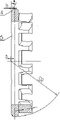
Fig. 1 is the structural representation of the utility model.
Fig. 2 is the sectional view of single outer guiding biplate solid cage.
Fig. 3 is the side view of single outer guiding monodactyle retainer.
Among the figure: 1, outer ring, 2, inner ring, 3, two half solid cages of outer guiding, 4, the slope, 5, the oil groove I, 6, the oil groove II.
Embodiment
As shown in Figure 1; And with reference to Fig. 2, Fig. 3; A kind of vibrating machine guides solid cage outward with selfaligning roller bearing; Described selfaligning roller bearing guides solid cage to comprise two half solid cages 3 of two outer guiding that are oppositely arranged outward, and has the gap between two two half solid cages 3 of outer guiding; Outside two, all have a plurality of oil groove I 5 along circle distribution on the two contacted end faces of half solid cage of guiding, guiding pair half solid cages contact and have a plurality of oil groove II 6 along circle distribution on the outer spherical surface of end face perpendicular to two outside; Two half solid cages of guiding contact and all have on the periphery of end face in order to increasing the slope 4 of lubrication effect outside two, the width h angle [alpha] on slope 4, and its value is fixed according to the retainer size; The outer diametric plane of two half solid cages of said outer guiding is a spherical cambered surface; In conjunction with Fig. 3; The minimum diameter place of the outer diametric plane of two half solid cages of outer guiding is the plane, and the length H maximum value of the outer diametric plane of two half solid cages of outer guiding is less than bearing outer ring rib internal diameter, and specific practice diametric(al) of diametric plane outside retainer is cut the top; Assurance is cut back, top H value less than bearing outer ring rib internal diameter, for the ease of the assembling of two half solid cages of outer guiding.
Selfaligning roller bearing guides retainer outward in use; Adopt and bearing outside raceway guidance mode; The retainer external diameter is a spherical cambered surface, after assembling outside two between the two half solid cage end faces of guiding the gap be 2s, sphere diameter SR is that bearing outside raceway diameter deducts two times guide clearance; Its centre of sphere is at bearing symmetry center place, so sphere center position is apart from retainer end face s.
Claims (1)
1. a vibrating machine guides solid cage outward with selfaligning roller bearing; It is characterized in that: described selfaligning roller bearing guides solid cage to comprise two half solid cages (3) of two outer guiding that are oppositely arranged outward, and has the gap between two two half solid cages (3) of outer guiding; Outside two, all have a plurality of oil groove I (5) along circle distribution on the two contacted end faces of half solid cage (3) of guiding, guiding pair half solid cages contact and have a plurality of oil groove II (6) along circle distribution on the outer spherical surface of end face perpendicular to two outside; Two half solid cages of guiding contact and all have in order to increase the slope (4) of lubrication effect on the periphery of end face outside two; The outer diametric plane of two half solid cages (3) of said outer guiding is a spherical cambered surface, and the maximum minor diameter place of the outer diametric plane of two half solid cages of outer guiding is the plane, and the length H maximum value of the outer diametric plane of two half solid cages of outer guiding is less than bearing outer ring rib internal diameter.
Priority Applications (1)
| Application Number | Priority Date | Filing Date | Title |
|---|---|---|---|
| CN2012200407495U CN202545587U (en) | 2012-02-09 | 2012-02-09 | External guiding solid cage of aligning roller bearing for vibrating machine |
Applications Claiming Priority (1)
| Application Number | Priority Date | Filing Date | Title |
|---|---|---|---|
| CN2012200407495U CN202545587U (en) | 2012-02-09 | 2012-02-09 | External guiding solid cage of aligning roller bearing for vibrating machine |
Publications (1)
| Publication Number | Publication Date |
|---|---|
| CN202545587U true CN202545587U (en) | 2012-11-21 |
Family
ID=47166227
Family Applications (1)
| Application Number | Title | Priority Date | Filing Date |
|---|---|---|---|
| CN2012200407495U Expired - Fee Related CN202545587U (en) | 2012-02-09 | 2012-02-09 | External guiding solid cage of aligning roller bearing for vibrating machine |
Country Status (1)
| Country | Link |
|---|---|
| CN (1) | CN202545587U (en) |
Cited By (1)
| Publication number | Priority date | Publication date | Assignee | Title |
|---|---|---|---|---|
| CN109322921A (en) * | 2018-11-27 | 2019-02-12 | 瓦房店轴承集团国家轴承工程技术研究中心有限公司 | The dedicated outer guidance Biserial cylindrical roller bearing of Vertical Mill |
-
2012
- 2012-02-09 CN CN2012200407495U patent/CN202545587U/en not_active Expired - Fee Related
Cited By (1)
| Publication number | Priority date | Publication date | Assignee | Title |
|---|---|---|---|---|
| CN109322921A (en) * | 2018-11-27 | 2019-02-12 | 瓦房店轴承集团国家轴承工程技术研究中心有限公司 | The dedicated outer guidance Biserial cylindrical roller bearing of Vertical Mill |
Similar Documents
| Publication | Publication Date | Title |
|---|---|---|
| CN201606411U (en) | Three-row cylinder roller bearing axial composite cage | |
| CN203214584U (en) | Guide rail-roller bearing | |
| CN202790088U (en) | Double-row full-complement cylindrical roller bearing | |
| CN202545587U (en) | External guiding solid cage of aligning roller bearing for vibrating machine | |
| CN103352919B (en) | Solid cage and reinforced solid tapered roller bearing | |
| CN103821822A (en) | Arc-shaped middle shaft cylindrical roller bearing | |
| CN103671507A (en) | High-bearing self-aligning roller bearing | |
| CN204284199U (en) | A kind of high rotating speed lightweight roller bearing | |
| JP2012219994A (en) | Rolling bearing | |
| CN106151265A (en) | A kind of multiple row is without the full ball self-aligning bearing of retainer | |
| CN202790087U (en) | Double-row full-complement cylindrical roller bearing | |
| CN104454970A (en) | Light-weight cylindrical roller bearing with high rotation speed | |
| CN203395023U (en) | Solid retainer and reinforced solid tapered roller bearing | |
| CN201083232Y (en) | Double-row column roller bearing with aligning ring | |
| CN211778514U (en) | Rolling bearing | |
| CN209838965U (en) | Lightweight retainer and ball bearing thereof | |
| CN102678758A (en) | Entity retainer of ball bearing | |
| CN203585101U (en) | Tapered roller bearing retainer | |
| JP2012172784A (en) | Ball bearing | |
| CN202790085U (en) | Bidirectional thrust self-aligning roller bearing | |
| CN103790932A (en) | Deep groove ball bearing based on concave cage | |
| CN207178465U (en) | A kind of spacing block of crossed roller bearing | |
| CN203130796U (en) | Stamping retainer aligning roller bearing with novel structure | |
| CN205260633U (en) | Oil ring guider | |
| CN203114909U (en) | Bearing retainer |
Legal Events
| Date | Code | Title | Description |
|---|---|---|---|
| C14 | Grant of patent or utility model | ||
| GR01 | Patent grant | ||
| CF01 | Termination of patent right due to non-payment of annual fee | ||
| CF01 | Termination of patent right due to non-payment of annual fee |
Granted publication date: 20121121 Termination date: 20130209 |