CN202543258U - Box-type quenching device - Google Patents
Box-type quenching device Download PDFInfo
- Publication number
- CN202543258U CN202543258U CN 201220008644 CN201220008644U CN202543258U CN 202543258 U CN202543258 U CN 202543258U CN 201220008644 CN201220008644 CN 201220008644 CN 201220008644 U CN201220008644 U CN 201220008644U CN 202543258 U CN202543258 U CN 202543258U
- Authority
- CN
- China
- Prior art keywords
- water
- casing
- collector
- steel plate
- box
- Prior art date
- Legal status (The legal status is an assumption and is not a legal conclusion. Google has not performed a legal analysis and makes no representation as to the accuracy of the status listed.)
- Expired - Fee Related
Links
Images


Abstract
A box-type quenching device belongs to the technical field of thermal treatment equipment and is used for quenching extra wide and extra thick steel plates. The technical scheme is as follows: the box-type quenching device consists of a box body, steel plate shelves, upper water spray manifolds and lower water spray manifolds; the external wall of the box body is of a reinforced concrete structure; the box body is fully filled with cooling water; a plurality of rows of the steel plate shelves are arranged in parallel at the bottom of the box body and used for placing the quenching steel plate; two side walls at two sides of the box body are provided with the upper water spray manifolds; the lower water spray manifolds are installed between the steel plate shelves; the upper water spray manifolds and the lower water spray manifolds are respectively provided with upper spray nozzles and lower spray nozzles; and overflow grooves are arranged at two sides of the upper end of the box body. The box-type quenching device has strong cooling strength, good cooling uniformity and controllable controlling speed, solves quenching problems of the extra wide and extra thick steel plates and can be used for quenching the steel plates with thickness of 400mm and width of 4200 mm; and the box-type quenching device has the advantages of simple structure, wide applicability, convenience in use, low installation and manufacturing cost, low failure rate, high degree of automation and long service life and the like.
Description
Technical field
The utility model relates to a kind of quenching apparatus that is used for extra wide, super-thick steel plate, belongs to the HTFX technical field.
Background technology
The thermal treatment of special steel material is the important step in the Iron and Steel Production; Along with the development of producing, market is increasing for extra wide, special thick quenched nickelclad demand, and extra wide, super-thick steel plate are because size is bigger; Need very big cooling intensity ability through hardening, traditional quenching device is difficult to reach requirement.The tradition quenching device comprises quenching pond and quenching press; No matter be quenching pond or quenching press; Have all that cooling intensity is little, cooling uniformity is poor and shortcoming such as speed of cooling is uncontrollable, use traditional quenching apparatus that extra wide, super-thick steel plate are quenched is a difficult problem in the industry always.Therefore, designing a kind of quenching device simple in structure, that cooling intensity is big, cooling uniformity good and speed of cooling is controlled is very important.
The utility model content
The utility model technical problem to be solved provides a kind of simple in structure, cooling intensity is big, cooling uniformity good and speed of cooling is controlled box quenching device.
The technical scheme that solves the problems of the technologies described above is:
A kind of box quenching device; It by casing, steel plate shelf, on spray water collector, the collector of spraying water is formed down, cabinet exterior is a skeleton construction, is full of water coolant in the casing; Bottom half is arranged side by side the steel plate shelf that plurality of rows is used to place quenched nickelclad; The inner side-wall of casing both sides is equipped with the water spray collector, and steel plate shelf below is equipped with down the water spray collector, on spray water collector be separately installed with upper spray nozzle and following nozzle on the water spray collector down.
Above-mentioned box quenching device, there is overflow groove the both sides, upper end of said casing, and overflow groove is outer wall along the casing both sides, and the bottom of overflow groove is lower than the top of cabinet exterior.
Above-mentioned box quenching device, the said water spray collector of going up is divided into two sections with the collector of spraying water down along the casing length direction, and every section is connected with water-supply line respectively.
Above-mentioned box quenching device is equipped with the water coolant temperature thermocouple in the said casing, the water coolant temperature thermocouple is connected with control computer.
The usefulness of the utility model is:
The utility model can be placed on the steel plate that needs to quench on the steel plate shelf; By last water spray collector and water spray collector water spray cooling down; Its cooling intensity is big, cooling uniformity good and speed of cooling is controlled; Solved the quenching difficult problem of extra wide, super-thick steel plate, hardenable steel plate thickness can reach 400mm, and width can reach 4200mm.The utlity model has simple in structure, suitability is wide, easy to use, low cost of manufacture, advantages such as failure rate is low, level of automation is high, long service life are installed.
Description of drawings
Fig. 1 is the structural representation of the utility model;
Fig. 2 is the vertical view of Fig. 1;
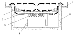
Fig. 3 is a water flows direction synoptic diagram in the casing.
Label is following among the figure: on spray water collector 1, upper spray nozzle 2, spray water collector 3, steel plate shelf 4, nozzle 5, quenched nickelclad 6, overflow groove 7, casing 8 down down.
Embodiment
The utility model by casing 8, steel plate shelf 4, on spray water collector 1, the collector 3 of spraying water is formed down.
Show among the figure that casing 8 outer walls are skeleton construction, are full of water coolant in the casing 8.
Show among the figure that casing 8 bottoms are arranged side by side plurality of rows steel plate shelf 4, quenched nickelclad 6 is placed on the steel plate shelf 4.
Show among the figure that the inner side-wall of casing 8 both sides is equipped with water spray collector 1, steel plate shelf 4 belows are equipped with down water spray collector 3, on spray water collector 1 be separately installed with upper spray nozzle 2 and following nozzle 5 on the water spray collector 3 down.In order to increase cooling intensity and flow of cooling water property; The collector 1 and the collector 3 long pressure inequalities that cause upper spray nozzle 2 and following nozzle 5 of spraying water down prevent to spray water; Last water spray collector 1 is divided into two sections with the collector 3 of spraying water down along casing 8 length directions, and every section is connected with water-supply line respectively.
Show among the figure that there is overflow groove 7 both sides, upper end of casing 8, overflow groove 7 is along casing 8 both sides outer walls, and the bottom of overflow groove 7 is lower than the top of casing 8 outer walls.High-temperature cooling water flows out through overflow groove 7, and returns to pumping plant through the drainage pipelines in the overflow groove 7 and to recycle.
Show among the figure that adopt the infrared thermometer thermometric before quenched nickelclad 6 entry, the record steel plate is gone into water temp.After quenched nickelclad 6 entry, its upper and lower surfaces respectively has 2 temperature thermocouples, is used to measure steel plate upper and lower surfaces thermometric.The water coolant temperature thermocouple is installed in the casing 8, and the water temperature that can measure casing 8 internal cooling water changes, and all temperature datas all can be recorded in the computingmachine.According to the temperature data of being surveyed, to different steel grades and processing requirement, the adjustable water coolant total flux and the collector throughput ratio of spraying water up and down are to optimize the performance perameter of quenched nickelclad 6.
The use of the utility model is following:
The quenched nickelclad that heats 6 via in crane for hoisting to the casing 8, is placed on the steel plate shelf 4, wait to put steady after; Open the valve of the water spray collector 1 and the collector 3 of spraying water down; Water coolant flows out through upper spray nozzle 2 and following nozzle 5, and current flow in casing 8, and low-temperature cooling water has been replaced by quenched nickelclad 6 warmed-up high-temperature cooling waters; And high-temperature cooling water drained in the overflow groove 7, return to pumping plant through the drainage pipelines in the overflow groove 7 again and recycle.
Claims (4)
1. box quenching device; It is characterized in that: it by casing (8), steel plate shelf (4), on spray water collector (1), the collector (3) of spraying water is formed down; Casing (8) outer wall is a skeleton construction; Casing is full of water coolant in (8), and casing (8) bottom is arranged side by side the steel plate shelf (4) that plurality of rows is used to place quenched nickelclad (6), and the inner side-wall of casing (8) both sides is equipped with water spray collector (1); Steel plate shelf (4) below is equipped with down water spray collector (3), on spray water and be separately installed with upper spray nozzle (2) and following nozzle (5) on collector (1) and the collector (3) of time spraying water.
2. box quenching device according to claim 1 is characterized in that: there is overflow groove (7) both sides, upper end of said casing (8), and overflow groove (7) is outer wall along casing (8) both sides, and the bottom of overflow groove (7) is lower than the top of casing (8) outer wall.
3. box quenching device according to claim 2 is characterized in that: the said upward water spray collector (1) and the collector (3) of spraying water down are divided into two sections along casing (8) length direction, and every section is connected with water-supply line respectively.
4. box quenching device according to claim 3 is characterized in that: said casing is equipped with the water coolant temperature thermocouple in (8), and the water coolant temperature thermocouple is connected with control computer.
Priority Applications (1)
| Application Number | Priority Date | Filing Date | Title |
|---|---|---|---|
| CN 201220008644 CN202543258U (en) | 2012-01-10 | 2012-01-10 | Box-type quenching device |
Applications Claiming Priority (1)
| Application Number | Priority Date | Filing Date | Title |
|---|---|---|---|
| CN 201220008644 CN202543258U (en) | 2012-01-10 | 2012-01-10 | Box-type quenching device |
Publications (1)
| Publication Number | Publication Date |
|---|---|
| CN202543258U true CN202543258U (en) | 2012-11-21 |
Family
ID=47163923
Family Applications (1)
| Application Number | Title | Priority Date | Filing Date |
|---|---|---|---|
| CN 201220008644 Expired - Fee Related CN202543258U (en) | 2012-01-10 | 2012-01-10 | Box-type quenching device |
Country Status (1)
| Country | Link |
|---|---|
| CN (1) | CN202543258U (en) |
Cited By (3)
| Publication number | Priority date | Publication date | Assignee | Title |
|---|---|---|---|---|
| CN103882199A (en) * | 2014-03-13 | 2014-06-25 | 广东坚宜佳五金制品有限公司 | Method and system for quenching and cooling ultra-long rod member |
| CN107385167A (en) * | 2017-09-12 | 2017-11-24 | 柳州市隆兴模具技术有限公司 | A kind of heat sink for quenching cooling oil |
| CN108034795A (en) * | 2017-11-11 | 2018-05-15 | 江阴兴澄特种钢铁有限公司 | A kind of design method of slab quenching apparatus |
-
2012
- 2012-01-10 CN CN 201220008644 patent/CN202543258U/en not_active Expired - Fee Related
Cited By (3)
| Publication number | Priority date | Publication date | Assignee | Title |
|---|---|---|---|---|
| CN103882199A (en) * | 2014-03-13 | 2014-06-25 | 广东坚宜佳五金制品有限公司 | Method and system for quenching and cooling ultra-long rod member |
| CN107385167A (en) * | 2017-09-12 | 2017-11-24 | 柳州市隆兴模具技术有限公司 | A kind of heat sink for quenching cooling oil |
| CN108034795A (en) * | 2017-11-11 | 2018-05-15 | 江阴兴澄特种钢铁有限公司 | A kind of design method of slab quenching apparatus |
Similar Documents
| Publication | Publication Date | Title |
|---|---|---|
| CN102865765B (en) | Single-tank heat-storage system and single-tank heat-storage method | |
| CN202543258U (en) | Box-type quenching device | |
| CN205088180U (en) | Coke oven crude gas tedge heat transfer device | |
| CN202202247U (en) | Concrete structure cooled by circulating water | |
| CN105273728A (en) | Raw gas riser pipe heat exchange device for coking furnace | |
| CN102072678B (en) | Water bath type gasifying device | |
| CN207192798U (en) | A kind of graphitizing furnace fast cooling structure | |
| CN202487184U (en) | Double-layer water rod device used for improving supercritical water cooled reactor performance | |
| CN201974067U (en) | Water-bath type gasifier | |
| CN202692758U (en) | Cement grinding aid afterheat water cooling device | |
| CN104827614A (en) | Cooling unit for modification process of long glass fiber reinforced plastic | |
| CN202056469U (en) | Prefabricated directly-buried thermal insulation pipe | |
| CN202131104U (en) | Bell jar and chassis of polycrystalline silicon reduction furnace | |
| CN203866339U (en) | High temperature slag heat recovering device | |
| CN104496821B (en) | Gasify in methylcarbonate production CO 2with the method reclaiming emptying material | |
| CN202808888U (en) | Constant temperature quenching device | |
| CN203187736U (en) | Energy-saving nitriding furnace | |
| CN203807518U (en) | Quenching and cooling system for ultra-long rod piece | |
| CN103882199A (en) | Method and system for quenching and cooling ultra-long rod member | |
| CN202482269U (en) | Heat-conducting oil circulation system in tar distillation | |
| CN203649317U (en) | Water-cooling vertical type lead anode casting mould plate | |
| CN203855610U (en) | Heat treatment quenching device | |
| CN104540257A (en) | Rapid oil-water heating device of oil conveying pipe | |
| CN205138254U (en) | High fructose syrup production cooling system of workshop section | |
| CN204007239U (en) | A kind of being applicable to compared with the tubular heat exchanger of low viscosity material |
Legal Events
| Date | Code | Title | Description |
|---|---|---|---|
| C14 | Grant of patent or utility model | ||
| GR01 | Patent grant | ||
| CF01 | Termination of patent right due to non-payment of annual fee |
Granted publication date: 20121121 Termination date: 20160110 |