CN202531359U - Wind power generating device for cities - Google Patents
Wind power generating device for cities Download PDFInfo
- Publication number
- CN202531359U CN202531359U CN2012202017802U CN201220201780U CN202531359U CN 202531359 U CN202531359 U CN 202531359U CN 2012202017802 U CN2012202017802 U CN 2012202017802U CN 201220201780 U CN201220201780 U CN 201220201780U CN 202531359 U CN202531359 U CN 202531359U
- Authority
- CN
- China
- Prior art keywords
- wind power
- fan
- power plant
- installation tube
- city
- Prior art date
- Legal status (The legal status is an assumption and is not a legal conclusion. Google has not performed a legal analysis and makes no representation as to the accuracy of the status listed.)
- Expired - Fee Related
Links
Images

Classifications
-
- Y—GENERAL TAGGING OF NEW TECHNOLOGICAL DEVELOPMENTS; GENERAL TAGGING OF CROSS-SECTIONAL TECHNOLOGIES SPANNING OVER SEVERAL SECTIONS OF THE IPC; TECHNICAL SUBJECTS COVERED BY FORMER USPC CROSS-REFERENCE ART COLLECTIONS [XRACs] AND DIGESTS
- Y02—TECHNOLOGIES OR APPLICATIONS FOR MITIGATION OR ADAPTATION AGAINST CLIMATE CHANGE
- Y02B—CLIMATE CHANGE MITIGATION TECHNOLOGIES RELATED TO BUILDINGS, e.g. HOUSING, HOUSE APPLIANCES OR RELATED END-USER APPLICATIONS
- Y02B10/00—Integration of renewable energy sources in buildings
- Y02B10/30—Wind power
-
- Y—GENERAL TAGGING OF NEW TECHNOLOGICAL DEVELOPMENTS; GENERAL TAGGING OF CROSS-SECTIONAL TECHNOLOGIES SPANNING OVER SEVERAL SECTIONS OF THE IPC; TECHNICAL SUBJECTS COVERED BY FORMER USPC CROSS-REFERENCE ART COLLECTIONS [XRACs] AND DIGESTS
- Y02—TECHNOLOGIES OR APPLICATIONS FOR MITIGATION OR ADAPTATION AGAINST CLIMATE CHANGE
- Y02E—REDUCTION OF GREENHOUSE GAS [GHG] EMISSIONS, RELATED TO ENERGY GENERATION, TRANSMISSION OR DISTRIBUTION
- Y02E10/00—Energy generation through renewable energy sources
- Y02E10/70—Wind energy
- Y02E10/74—Wind turbines with rotation axis perpendicular to the wind direction
Abstract
The utility model discloses a wind power generating device for cities. The wind power generating device comprises a disk generator, a support and a fan mounting barrel installed on the support. The fan mounting barrel is installed on the support through a center suspension vertical shaft, at least three fans are installed on the surface of the fan mounting barrel, included angles are formed between the fans and the radial direction of the cross section of the fan mounting barrel, the bottom end of the center suspension vertical shaft is fixedly connected with a rotor of the disk generator, and the disk generator is connected with a storage battery pack through a conducting sliding ring. The included angles are formed between the fans and the an mounting barrel so that the problems occurring in windward guiding are solved, air sources in different directions are utilized better, all wind power resources are utilized at 360 degrees, the wind power generating device is wide in applied range, the wind power utilization rate is greatly improved particularly in the cities, and the wind power generating device conforms to the general trend of environment protection, energy saving and consumption reduction nowadays.
Description
Technical field
The utility model belongs to power domain, is a kind of middle-size and small-size wind power plant that is suitable for use in the city specifically.
Background technique
At present; The wind-driven generator of market sale is a lot, has a lot of wind power plants in windy and spacious countries and regions, is equipped with a lot of wind power plants like the Holland and the Midwest of China; Yet these wind power plants have certain region restriction in use; Such as the number of the weather of blowing and the stability problem of wind direction, present wind-driven generator adopt driftage equipment so that the windmill impeller can kibli to, yet in the city since building just stand in great numbers; So the change of wind direction is very frequent, so this wind-driven generator is not adapted at using in the city; The vacant area in incity, city is very little; The fan of usual wind-driven generator is in order to obtain bigger stress surface; It is all very long that fan is done, so utilization area greatly also is the reason that existing wind-driven generator can not be popularized in the city, therefore very low to utilization ratio of wind energy in the city.
Summary of the invention
The purpose of the utility model is to provide a kind of wind power plant that supplies the city to use, to solve the problem that incity, city wind energy can not get efficient usefulness.
The utility model adopts following technological scheme:
Wind power plant is used in a kind of city; Comprise disk generator, support and rack-mount fan installation tube; Said fan installation tube is rack-mount through the center suspension vertical shaft, and the mounted on surface of said fan installation tube has at least three fans, and the cross section of said fan and said fan installation tube has angle between radially; The bottom of said center suspension vertical shaft is fixedly connected with the rotor of a disk generator, and said disk generator connects battery pack through conducting slip ring.
Wind power plant is used in above-mentioned city, and said fan is welded on the surface of said fan installation tube, and the angle that each said fan and fan installation tube cross section form between radially is all identical.
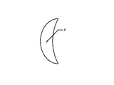
Wind power plant is used in above-mentioned city, and said wafter outer rim is an ellipse arc, one side said fan and the welding of said fan installation tube has and the corresponding shape of said fan installation tube.
Wind power plant is used in above-mentioned city, and said fan installation tube is cylindrical structure or oval structure.
Wind power plant is used in above-mentioned city, and said support comprises underframe and installation frame, and said installation frame is installed on the said underframe through bolt.
Wind power plant is used in above-mentioned city, and the top of the top of said installation frame and said center suspension vertical shaft links together through flange plate bearing.
Wind power plant is used in above-mentioned city, and said installation frame is made up of at least two suspension strut beams.
Wind power plant is used in above-mentioned city, and said every suspension strut beam is the arc camber beam, and an end of said arc camber beam is installed on the said flange plate bearing, and the other end of said arc camber beam is installed on the said underframe through bolt.
Wind power plant is used in above-mentioned city, and the angle that forms between said fan and the said fan installation tube is greater than 20 °, smaller or equal to 70 degree.
The beneficial effect of the utility model: the city is with forming the problem that angle has solved the guiding of facining the wind between the fan of wind power plant and the fan installation tube; Better utilization different direction scrape the wind regime that comes; Utilize all wind resources with 360 degree angles; Applicable scope is extensive, especially in the city, wind energy utilization is improved a lot, the current environmental protection of loading, energy-saving and cost-reducing main trend.
Description of drawings
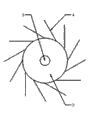
Fig. 1 is the structural representation of the utility model city with wind power plant,
Fig. 2 is fan and the fan installation tube annexation schematic representation of the utility model city with wind power plant,
Fig. 3 is the fan structure schematic representation of the utility model city with wind power plant.
Among the figure, 1-disk generator, 2-fan installation tube, 3-center suspension vertical shaft, 4-fan, 5-conducting slip ring, 6-battery pack, 7-underframe, 8-flange plate bearing, 9-suspension strut beam.
Embodiment
Through specific embodiment the utility model is described in further detail below, to help the content of understanding the utility model.
As shown in Figure 1, wind power plant is used in a kind of city, comprises disk generator 1, support and rack-mount fan installation tube 2; Said fan installation tube 2 is oval, and said fan installation tube 2 is rack-mount through center suspension vertical shaft 3, and said support comprises underframe 7 and installation frame; Said installation frame is installed on the said underframe 7 through bolt, and the top of the top of said installation frame and said center suspension vertical shaft 3 links together through flange plate bearing 8, and said installation frame is made up of two suspension strut beams 9; Said every suspension strut beam 9 is the arc camber beam; One end of said arc camber beam is installed on the said flange plate bearing 8, and the other end of said arc camber beam is installed on the said underframe 7, as shown in Figures 2 and 3 through bolt; The mounted on surface of said fan installation tube 2 has 12 fans 4; Said fan 4 is welded on the surface of said fan installation tube 2, and said fan 4 outer rims are ellipse arc, and the angle that each said fan 4 and fan installation tube 2 cross sections form between radially is all identical; The cross section of said fan 4 and said fan installation tube 2 has 60 ° of angles between radially; The bottom of said center suspension vertical shaft 3 is fixedly connected with the rotor of disk generator 1, and said disk generator 1 connects battery pack 6 through conducting slip ring 5, makes wind from which direction blows and can both rotational power be provided for fan 4 no matter 12 fans 4 evenly distribute on fan installation tube 2 surfaces; And there are 60 ° angle in fan 4 and fan installation tube 2 between radially; From center suspension vertical shaft 3 is the boundary, and fan 4 windward sides of center suspension vertical shaft 3 one sides all can make fan 4 and fan installation tube 2 rotate greater than the area of opposite side fan 4 windward sides so no matter wind from which direction blows over to fan 4; Fan installation tube 2 is rotated and is driven 3 rotations of center suspension vertical shaft; Center suspension vertical shaft 3 drives the rotor rotation of disk generator 1, and then disk generator 1 begins generating, and the conducting slip ring 5 of disk generator 1 below stores power delivery through lead to battery pack 6; When needing electricity consumption, battery pack 6 is connected consumer get final product; Because incity, city wind-force does not have the wind-force of open space powerful; So the electric energy that is transformed with this wind power plant maybe and be not suitable for the big equipment use of power consumption; Can the electric energy that this wind power plant is transformed be supplied the low low power consuming devices of power consumption to use, as be built up in the street lamp of highway both sides.
The foregoing description only be for clearly explain the utility model create done for example, and be not the qualification of the utility model being created embodiment.For the those of ordinary skill in affiliated field, on the basis of above-mentioned explanation, can also make other multi-form variation or change.Here need not also can't give exhaustive to all mode of executions.Any conspicuous variation of being extended out within all spirit and principles at the utility model or change still are in the utility model and create among the protection domain of claim.
Claims (9)
1. wind power plant is used in a city; It is characterized in that; Comprise disk generator (1), support and rack-mount fan installation tube (2); Said fan installation tube (2) is rack-mount through center suspension vertical shaft (3), and the mounted on surface of said fan installation tube (2) has at least three fans (4), and the cross section of said fan (4) and said fan installation tube (2) has angle between radially; The bottom of said center suspension vertical shaft (3) is fixedly connected with the rotor of said disk generator (1), and said disk generator (1) connects battery pack (6) through conducting slip ring (5).
2. wind power plant is used in city according to claim 1; It is characterized in that; Said fan (4) is welded on the surface of said fan installation tube (2), and the angle that each said fan (4) and said fan installation tube (2) cross section form between radially is all identical.
3. wind power plant is used in city according to claim 2; It is characterized in that; Said fan (4) outer rim is an ellipse arc, and said fan (4) and said fan installation tube (2) are one side the having and the corresponding shape of said fan installation tube (2) of welding.
4. wind power plant is used in city according to claim 3, it is characterized in that, said fan installation tube (2) is cylindrical structure or oval structure.
5. wind power plant is used in city according to claim 4, it is characterized in that, said support comprises underframe (7) and installation frame, and said installation frame is installed on the said underframe (7) through bolt.
6. wind power plant is used in city according to claim 5, it is characterized in that, the top of the top of said installation frame and said center suspension vertical shaft (3) links together through flange plate bearing (8).
7. want 6 to ask described city to use wind power plant according to right, it is characterized in that, said installation frame is made up of at least two suspension strut beams (9).
8. wind power plant is used in city according to claim 7; It is characterized in that; Said suspension strut beam (9) is the arc camber beam, and an end of said arc camber beam is installed on the said flange plate bearing (8), and the other end of said arc camber beam is installed on the said underframe (7) through bolt.
9. use wind power plant according to the arbitrary described city of the said 1-8 of claim, it is characterized in that, the angle that forms between said fan (4) and the said fan installation tube (2) is greater than 20 °, smaller or equal to 70 degree.
Priority Applications (1)
| Application Number | Priority Date | Filing Date | Title |
|---|---|---|---|
| CN2012202017802U CN202531359U (en) | 2012-05-08 | 2012-05-08 | Wind power generating device for cities |
Applications Claiming Priority (1)
| Application Number | Priority Date | Filing Date | Title |
|---|---|---|---|
| CN2012202017802U CN202531359U (en) | 2012-05-08 | 2012-05-08 | Wind power generating device for cities |
Publications (1)
| Publication Number | Publication Date |
|---|---|
| CN202531359U true CN202531359U (en) | 2012-11-14 |
Family
ID=47132548
Family Applications (1)
| Application Number | Title | Priority Date | Filing Date |
|---|---|---|---|
| CN2012202017802U Expired - Fee Related CN202531359U (en) | 2012-05-08 | 2012-05-08 | Wind power generating device for cities |
Country Status (1)
| Country | Link |
|---|---|
| CN (1) | CN202531359U (en) |
Cited By (4)
| Publication number | Priority date | Publication date | Assignee | Title |
|---|---|---|---|---|
| CN103397988A (en) * | 2013-07-23 | 2013-11-20 | 钟明华 | Vertical wall type wind power hanger |
| CN103410669A (en) * | 2013-07-23 | 2013-11-27 | 钟明华 | Wall-attaching type wind-driven generator |
| CN103967819A (en) * | 2014-05-26 | 2014-08-06 | 浙江理工大学 | Omni-directional fan with denoising function |
| CN109699607A (en) * | 2019-02-22 | 2019-05-03 | 张敬 | A kind of convenient regulating type Trypetid trapper |
-
2012
- 2012-05-08 CN CN2012202017802U patent/CN202531359U/en not_active Expired - Fee Related
Cited By (7)
| Publication number | Priority date | Publication date | Assignee | Title |
|---|---|---|---|---|
| CN103397988A (en) * | 2013-07-23 | 2013-11-20 | 钟明华 | Vertical wall type wind power hanger |
| CN103410669A (en) * | 2013-07-23 | 2013-11-27 | 钟明华 | Wall-attaching type wind-driven generator |
| CN103397988B (en) * | 2013-07-23 | 2015-11-18 | 钟明华 | Vertical wall type wind power hanger |
| CN103410669B (en) * | 2013-07-23 | 2015-11-18 | 钟明华 | Wall-attachment wind-driven generator |
| CN103967819A (en) * | 2014-05-26 | 2014-08-06 | 浙江理工大学 | Omni-directional fan with denoising function |
| CN103967819B (en) * | 2014-05-26 | 2016-08-24 | 浙江理工大学 | A kind of 360 ° of fans of noise reduction |
| CN109699607A (en) * | 2019-02-22 | 2019-05-03 | 张敬 | A kind of convenient regulating type Trypetid trapper |
Similar Documents
| Publication | Publication Date | Title |
|---|---|---|
| CN101709845B (en) | Self-powered environmental-friendly street lamp and square lamp | |
| CN101710469B (en) | Self-powered environmental-friendly billboard and television advertisement stage | |
| CN202531359U (en) | Wind power generating device for cities | |
| US20120019002A1 (en) | Vertical axial wind power generation device | |
| CN104847579A (en) | Adjustable-blade-attack-angle vertical-axis wind turbine with double-layer wind wheels | |
| CN104779896A (en) | Photovoltaic wind generating set | |
| CN201155429Y (en) | Low resistance vertical shaft wind power plant | |
| WO2011095054A1 (en) | High-efficiency high-power vertical axis wind generator | |
| CN202832977U (en) | Balanced vertical axis wind generating set | |
| JP3163267U (en) | Vertical axis wind power generator | |
| JP2013519022A (en) | High efficiency, high power vertical axis wind power generator | |
| CN201412276Y (en) | Dual-purpose wind driven generator used for air change and illumination | |
| CN207029982U (en) | A kind of anti-transport deformation device of wind turbine tower | |
| CN105553176A (en) | Magnetic levitation device for vertical-axis wind turbine | |
| CN202659422U (en) | Magnetic suspension wind driven generator | |
| CN101644231B (en) | Wind power generator with dual purposes of ventilation and illumination | |
| CN205064188U (en) | Solar cell panel fixing device and including its aerogenerator pylon | |
| JP2011185101A (en) | Wind power generation device and wind power generation device assembly using the same | |
| CN205155821U (en) | Wind power generation's complementary power supply street lamp of scene is organized perpendicularly to multiunit | |
| CN205090324U (en) | Wind power generation's complementary power supply street lamp of scene is organized perpendicularly to multiunit | |
| CN104033333A (en) | Point and pocket type fan blades and automatic swing device enabling vertical shaft windmill to be efficient | |
| CN1670363A (en) | Magnetic suspension driving apparatus with arbor wheel and turbine for wind energy electricity generation | |
| CN113187666A (en) | Wind power generation equipment and system | |
| CN205001121U (en) | Utilize wind wheel structure of freewheel clutch transmission moment of torsion among aerogenerator | |
| CN204652287U (en) | Photovoltaic wind turbine generator |
Legal Events
| Date | Code | Title | Description |
|---|---|---|---|
| C14 | Grant of patent or utility model | ||
| GR01 | Patent grant | ||
| CF01 | Termination of patent right due to non-payment of annual fee |
Granted publication date: 20121114 Termination date: 20170508 |
|
| CF01 | Termination of patent right due to non-payment of annual fee |