CN202528390U - Programmable logic controller (PLC)-control-based double-layer injection mold - Google Patents
Programmable logic controller (PLC)-control-based double-layer injection mold Download PDFInfo
- Publication number
- CN202528390U CN202528390U CN2012200267894U CN201220026789U CN202528390U CN 202528390 U CN202528390 U CN 202528390U CN 2012200267894 U CN2012200267894 U CN 2012200267894U CN 201220026789 U CN201220026789 U CN 201220026789U CN 202528390 U CN202528390 U CN 202528390U
- Authority
- CN
- China
- Prior art keywords
- injection portion
- double
- mold
- injection
- plc
- Prior art date
- Legal status (The legal status is an assumption and is not a legal conclusion. Google has not performed a legal analysis and makes no representation as to the accuracy of the status listed.)
- Expired - Lifetime
Links
Images


Abstract
The utility model provides a programmable logic controller (PLC)-control-based double-layer injection mold. The double-layer injection mold comprises a first injection part and a second injection part. Main body structures of the two injection parts are the same, and forming cavities formed by female and male mold cores can be different. The mold closing surfaces and ejector mechanisms of the two injection parts are controlled by a PLC. During the mold opening of each time, only one mold closing surface is opened, mold opening, mold closing and ejection action are executed, then the mold closing surface of the other injection part still executes mold closing cooling action, and the two injection parts are not interfered. Therefore, time can be comprehensively arranged, and yield can be approximately doubled.
Description
Technical field
The present invention relates to a kind of mould of thermoplastic, be specifically related to a kind of double-layer injection mold of the PLC of employing control.
Background technology
Plastic products have advantages such as moulding is fast, light weight, obtain very fast development in recent years.The forming method of plastic products has a lot, like injection moulding, blowing etc.The profiled part of injection mold mainly comprises male model plate and caster, and male model plate and caster constitute the forming cavity of product, and in order to enhance productivity, the technical staff generally is provided with many composition die cavities in the feature die plate, thus a plurality of products of one-shot forming.But; The double stack mold of synchronous opening is all adopted in the injection mo(u)lding of general thermoplastic, and open synchronously double stack mold can cause mould in cool time, can't devote oneself to work, and this section period can be wasted; If can rationally adjust mould; In cool time, also can carry out injection operation, then can shorten molding cycle greatly, promote the production efficiency of injection mo(u)lding product.
Summary of the invention
The object of the invention is to provide a kind of double-layer injection mold of PLC control; It is used the two-layer mould in the double-layer injection mold respectively, when the product in one deck mould cools off, can carry out injection moulding to another layer mould; Thereby can shorten molding cycle, promote production efficiency.
In order to solve these problems of the prior art, technical scheme provided by the invention is:
A kind of double-layer injection mold of PLC control; Described mould is double-deck, and said double stack mold comprises first injection portion and second injection portion, and first injection portion of said double stack mold, the agent structure of second injection portion are identical; First injection portion, second injection portion include land area, male model plate, caster, male model benevolence, mother module core and mould pin; Described male model plate, caster all are fixed on the mould pin, and the outer wall of caster is provided with cast gate, and one of cast gate is communicated with mother module core; The other end of cast gate is communicated with TOP-TIP; The shared cover TOP-TIP of first injection portion of said double stack mold and second injection portion, the switching of the land area of said first injection portion and second injection portion is controlled by PLC, is equipped with ejecting mechanism in said first injection portion and second injection portion; Said male model plate drives by ejecting mechanism, and said ejecting mechanism is controlled by PLC.
Detailed technical scheme is: a kind of double-layer injection mold of PLC control, described mould are double-deck, and said double stack mold comprises first injection portion and second injection portion; First injection portion of said double stack mold, the agent structure of second injection portion are identical, and first injection portion, second injection portion include land area, male model plate, caster, male model benevolence, mother module core and mould pin, and described male model plate, caster all are fixed on the mould pin; The outer wall of caster is provided with cast gate, and one of cast gate is communicated with mother module core, and the other end of cast gate is communicated with TOP-TIP; The shared cover TOP-TIP of first injection portion of said double stack mold and second injection portion, the switching of the land area of said first injection portion and second injection portion is controlled by PLC, is equipped with ejecting mechanism in said first injection portion and second injection portion; Said male model plate drives by ejecting mechanism, and said ejecting mechanism is controlled by PLC, and TOP-TIP comprises runner, the adapter sleeve of being located at the hot runner manifold middle part and is used for the sprue bush that molten plastic is injected into mould; Runner communicates with cast gate on the caster, and said runner is connected with sprue bush through adapter sleeve, and said ejecting mechanism comprises ejector retainner plate and is located at the thimble on the ejector retainner plate; Said ejector retainner plate is driven by cylinder; The switch of said cylinder is controlled by PLC, and an end of said thimble is fixed on the ejector retainner plate, and the other end of thimble passes the below that the male model plate is connected to male model benevolence; Be provided with two groups of cylinders in the described double stack mold; Two groups of cylinders that are fixed on the mould pin are located at the mould both sides symmetrically, and the mould both sides also are provided with guide rod respectively, and ejector retainner plate can slide along guide rod under cylinder drives; Described double stack mold also comprises seat board; Said seat board is located at the outside of ejector retainner plate, and said seat board links to each other with male model plate, the caster of double stack mold through screw, and the outside of said seat board is provided with thermal insulation board; The direction that said seat board points to ejector retainner plate is provided with and ejects locating piece, saidly ejects the position that locating piece is used to limit ejector retainner plate.
As replenishing, be provided with cooling system in the said double stack mold, said cooling system is used for accelerating the cooling and shaping of mould product.
With respect to scheme of the prior art, advantage of the present invention is:
1. the described mould of the utility model is the double stack mold that comprises first injection portion and second injection portion, and the agent structure of two injection portion is identical, and the formed forming cavity of feature die benevolence then can be different; The land area of two injection portion and ejecting mechanism are controlled by PLC all; During each die sinking, only open a land area, carry out the switch mould again and eject action; This moment, the land area of another injection portion was also carried out mold closing cooling action; Two injection portion are not disturbed mutually, and then realize temporal overall arrangement, therefore just can increase about one times production capacity;
2. the utility model whole process using PLC controls, and only needs to configure parameters in operation first, can realize completely operation automatically, easy realization simple in structure.
Description of drawings
Below in conjunction with accompanying drawing and embodiment the present invention is further described:
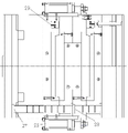
Fig. 1, Fig. 2 are the overall structure figure of the double-layer injection mold of present embodiment;
Partial section when Fig. 3 to Fig. 8 is the injection mold moulding of present embodiment;
Wherein: 1, product; 2, product, 3, male model benevolence; 4, mother module core; 5, mother module core; 6, male model benevolence; 7, TOP-TIP; 8, male model plate; 9, caster; 10, caster; 11, male model plate; 12, seat board; 13, seat board; 14, mould pin; 15, mould pin; 16, ejector retainner plate; 17, thimble; 18, ejector retainner plate; 19, thimble; 20, runner; 21, adapter sleeve; 22, sprue bush; 23, thermal insulation board; 24, eject locating piece; 25, cylinder; 26, cooling system; 27, guide rod; 28, guide rod; 29, counter.
The specific embodiment
Below in conjunction with specific embodiment such scheme is further specified.Should be understood that these embodiment are used to the present invention is described and are not limited to limit scope of the present invention.The implementation condition that adopts among the embodiment can be done further adjustment according to the condition of concrete producer, and not marked implementation condition is generally the condition in the normal experiment.
Embodiment:
Structure such as Fig. 1, shown in Figure 2 of the double-layer injection mold of the described PLC control of present embodiment; Described mould is double-deck; Said double stack mold comprises first injection portion and second injection portion; First injection portion of said double stack mold, the agent structure of second injection portion are identical; First injection portion comprises that land area A, male model plate 8, caster 9, male model benevolence 3, mother module core 4 and mould pin 14, the second injection portion include land area B, male model plate 11, caster 10, male model benevolence 6, mother module core 5 and mould pin 15.With first injection portion is example, and described male model plate 8, caster 9 all are fixed on the mould pin 14, and the outer wall of caster 9 is provided with cast gate, and one of cast gate is communicated with mother module core 4, and the other end of cast gate is communicated with TOP-TIP 7.
The shared cover TOP-TIP of first injection portion of said double stack mold and second injection portion; The switching of the land area of said first injection portion and second injection portion is controlled by PLC all; Be equipped with ejecting mechanism in said first injection portion and second injection portion, said male model plate 8, male model plate 11 drive by ejecting mechanism.Ejecting mechanism is controlled by PLC, and the ejecting mechanism of second injection portion comprises ejector retainner plate 18 and be located at the thimble 19 on the ejector retainner plate that said ejector retainner plate 18 is driven by cylinder 25; Be provided with two groups of cylinders 25 in the described double stack mold; Two groups of cylinders 25 that are fixed on the mould pin are located at the mould both sides symmetrically, and the mould both sides also are provided with guide rod 27 and guide rod 28 respectively, and ejector retainner plate 18 can slide along two guide rods under cylinder 25 drives; Balance and stability when the cylinder of both sides moves simultaneously and can guarantee that ejector retainner plate is advanced; The switch of said cylinder 25 is controlled by PLC, and an end of said thimble 19 is fixed on the ejector retainner plate 18, and the other end of thimble 19 passes the below that male model plate 11 is connected to male model benevolence 6; Described double stack mold also comprises seat board 12 and seat board 13; Said seat board all is located at the outside of ejector retainner plate, and said seat board links to each other with male model plate, the caster of double stack mold through screw, and the outside of said seat board is equipped with thermal insulation board.
The ejecting mechanism of first injection portion comprises ejector retainner plate 16 and is located at the thimble 17 on the ejector retainner plate 16; Same ejector retainner plate 16 can slide along two guide rods under cylinder 25 drives; The seat board 12 of first injection portion points to ejector retainner plates 16 and upwards is provided with and ejects locating piece 24, saidly ejects the position that locating piece 24 is used to limit ejector retainner plate 16.
TOP-TIP 7 comprises runner 20, the adapter sleeve 21 of being located at hot runner manifold middle part and is used for the sprue bush 22 that molten plastic is injected into mould, and runner 20 communicates with cast gate on the caster, and said runner 20 is connected with sprue bush 22 through adapter sleeve 21.
As replenishing, be provided with cooling system 26 in the said double stack mold, said cooling system 26 is used for accelerating the cooling and shaping of mould product.
The concrete injection mo(u)lding course of work is following:
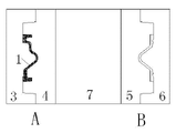
Fig. 3 shows the land area A of first injection portion and the land area B closure of second injection portion, and product 1 is in pressurize, cooling stage, and this moment, the forming cavity of second injection portion was not injected;
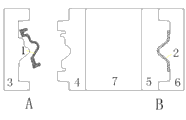
Fig. 4 shows that the land area A of first injection portion opens, and PLC control ejector retainner plate travels forward, and thimble ejects product 1, and the closed interior product 2 of land area B of second injection portion is injected simultaneously;
Fig. 5 shows that the land area A of first injection portion opens, and product 1 is removed, and also shows that the second dispensing end land area B is closed simultaneously, and product 2 is in pressurize, cooling stage;
Fig. 6 shows that the land area A of first injection portion closes, and the forming cavity of first injection portion is not injected, and the second injection portion land area B is closed simultaneously, and product 2 still is in pressurize, cooling stage;
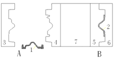
Fig. 7 shows that the land area B of second injection portion opens, and PLC control ejector retainner plate travels forward, and thimble ejects product 2, and the closed interior product 1 of land area A of first injection portion is injected simultaneously;
Fig. 8 shows that the land area B of second injection portion opens, and product 2 is removed, and also shows that the first dispensing end land area B is closed simultaneously, and product 1 is in pressurize, cooling stage;
So promptly realize once circulation, get into following one-period, i.e. Fig. 3 institute display action.
Also be provided with counter 29 in the described double stack mold of present embodiment, the switching of the land area in the mould is monitored, in order to calculate the product quantity of being produced.
Above-mentioned instance only is explanation technical conceive of the present invention and characteristics, and its purpose is to let the people who is familiar with this technology can understand content of the present invention and enforcement according to this, can not limit protection scope of the present invention with this.All equivalent transformations that spirit is done according to the present invention or modification all should be encompassed within protection scope of the present invention.
Claims (7)
1. the double-layer injection mold of a PLC control is characterized in that, described mould is double-deck; Said double stack mold comprises first injection portion and second injection portion; First injection portion of said double stack mold, the agent structure of second injection portion are identical, and first injection portion, second injection portion include land area, male model plate, caster, male model benevolence, mother module core and mould pin, and described male model plate, caster all are fixed on the mould pin; The outer wall of caster is provided with cast gate; One of cast gate is communicated with mother module core, and the other end of cast gate is communicated with TOP-TIP, the shared cover TOP-TIP of first injection portion of said double stack mold and second injection portion; The switching of the land area of said first injection portion and second injection portion is controlled by PLC; Be equipped with ejecting mechanism in said first injection portion and second injection portion, said male model plate drives by ejecting mechanism, and said ejecting mechanism is controlled by PLC.
2. the double-layer injection mold of PLC control according to claim 1; It is characterized in that; TOP-TIP comprises runner, the adapter sleeve of being located at the hot runner manifold middle part and is used for the sprue bush that molten plastic is injected into mould; Runner communicates with cast gate on the caster, and said runner is connected with sprue bush through adapter sleeve.
3. the double-layer injection mold of PLC control according to claim 1; It is characterized in that; Said ejecting mechanism comprises ejector retainner plate and is located at the thimble on the ejector retainner plate, and said ejector retainner plate is driven by cylinder, and the switch of said cylinder is controlled by PLC; One end of said thimble is fixed on the ejector retainner plate, and the other end of thimble passes the below that the male model plate is connected to male model benevolence.
4. the double-layer injection mold of PLC control according to claim 3; It is characterized in that described double stack mold also comprises seat board, said seat board is located at the outside of ejector retainner plate; Said seat board links to each other with male model plate, the caster of double stack mold through screw, and the outside of said seat board is provided with thermal insulation board.
5. the double-layer injection mold of PLC according to claim 4 control is characterized in that, the direction that said seat board points to ejector retainner plate is provided with and ejects locating piece, saidly ejects the position that locating piece is used to limit ejector retainner plate.
6. the double-layer injection mold of PLC control according to claim 3; It is characterized in that, be provided with two groups of cylinders in the described double stack mold, two groups of cylinders that are fixed on the mould pin are located at the mould both sides symmetrically; The mould both sides also are provided with guide rod respectively, and ejector retainner plate can slide along guide rod under cylinder drives.
7. the double-layer injection mold of PLC control according to claim 1 is characterized in that be provided with cooling system in the said double stack mold, said cooling system is used for accelerating the cooling and shaping of mould product.
Priority Applications (1)
| Application Number | Priority Date | Filing Date | Title |
|---|---|---|---|
| CN2012200267894U CN202528390U (en) | 2012-01-20 | 2012-01-20 | Programmable logic controller (PLC)-control-based double-layer injection mold |
Applications Claiming Priority (1)
| Application Number | Priority Date | Filing Date | Title |
|---|---|---|---|
| CN2012200267894U CN202528390U (en) | 2012-01-20 | 2012-01-20 | Programmable logic controller (PLC)-control-based double-layer injection mold |
Publications (1)
| Publication Number | Publication Date |
|---|---|
| CN202528390U true CN202528390U (en) | 2012-11-14 |
Family
ID=47129596
Family Applications (1)
| Application Number | Title | Priority Date | Filing Date |
|---|---|---|---|
| CN2012200267894U Expired - Lifetime CN202528390U (en) | 2012-01-20 | 2012-01-20 | Programmable logic controller (PLC)-control-based double-layer injection mold |
Country Status (1)
| Country | Link |
|---|---|
| CN (1) | CN202528390U (en) |
Cited By (2)
| Publication number | Priority date | Publication date | Assignee | Title |
|---|---|---|---|---|
| CN109228173A (en) * | 2018-09-20 | 2019-01-18 | 昆山弘正电子科技有限公司 | The injection mold of handle and the Shooting Technique of handle |
| CN109228208A (en) * | 2018-09-20 | 2019-01-18 | 昆山弘正电子科技有限公司 | The injection mold of router base and the Shooting Technique of router base |
-
2012
- 2012-01-20 CN CN2012200267894U patent/CN202528390U/en not_active Expired - Lifetime
Cited By (2)
| Publication number | Priority date | Publication date | Assignee | Title |
|---|---|---|---|---|
| CN109228173A (en) * | 2018-09-20 | 2019-01-18 | 昆山弘正电子科技有限公司 | The injection mold of handle and the Shooting Technique of handle |
| CN109228208A (en) * | 2018-09-20 | 2019-01-18 | 昆山弘正电子科技有限公司 | The injection mold of router base and the Shooting Technique of router base |
Similar Documents
| Publication | Publication Date | Title |
|---|---|---|
| CN101254642A (en) | Dual-color one-shot forming injection mold and injection molding method thereof | |
| CN103737857A (en) | Composite core pulling type precision mold | |
| CN108688080A (en) | A kind of line position hot mouth injection mold | |
| CN104890199A (en) | Demolding mechanism and injection mold for cup handle | |
| CN102179903A (en) | Hot-runner-technology-based three-plate injection mold | |
| CN202079728U (en) | Three-plate injection mould based on hot runner technique | |
| CN202528390U (en) | Programmable logic controller (PLC)-control-based double-layer injection mold | |
| CN102179898A (en) | Double-material die of small plastic parts and forming method of die | |
| CN109551712A (en) | Four lower dies of upper mold mold-opening structure Composite bottle cap injection mold twice | |
| CN203792642U (en) | Injection mold flowing channel structure | |
| CN104608335A (en) | Injection mold of double-color bottle and manufacturing technology of double-color bottle | |
| CN202702512U (en) | Injection mould for manufacturing programmable logic controller (PLC) cover | |
| CN203171965U (en) | Full-automatic progressive precision injection mold frame | |
| CN202781598U (en) | Double-mold synchronous injection molding machine | |
| CN202155999U (en) | Injection mould with submarine gates | |
| CN205871083U (en) | Stromatolite formula precise injection mold | |
| CN115339056A (en) | Secondary injection mold | |
| CN203567081U (en) | Injection mold for automobile washing cover plate | |
| CN114043665A (en) | Double-colored injection mold is used in production of double-deck product | |
| CN203092973U (en) | Ejecting mechanism | |
| CN205255424U (en) | Door inside lining forming die | |
| CN109093964A (en) | Plastics tapered end injection mold and plastics tapered end Shooting Technique | |
| CN216032244U (en) | Injection mold for producing luggage case shell | |
| CN204604740U (en) | A kind of automatic demoulding injection mold of thermos flask mouth | |
| CN208664290U (en) | A kind of refrigerator drawer cover molding die |
Legal Events
| Date | Code | Title | Description |
|---|---|---|---|
| C14 | Grant of patent or utility model | ||
| GR01 | Patent grant | ||
| CX01 | Expiry of patent term | ||
| CX01 | Expiry of patent term |
Granted publication date: 20121114 |