CN202524002U - Mechanical interlocking mechanism of removable switch cabinet - Google Patents
Mechanical interlocking mechanism of removable switch cabinet Download PDFInfo
- Publication number
- CN202524002U CN202524002U CN2012200753093U CN201220075309U CN202524002U CN 202524002 U CN202524002 U CN 202524002U CN 2012200753093 U CN2012200753093 U CN 2012200753093U CN 201220075309 U CN201220075309 U CN 201220075309U CN 202524002 U CN202524002 U CN 202524002U
- Authority
- CN
- China
- Prior art keywords
- circuit breaker
- switch cabinet
- interlocking mechanism
- connecting rod
- guide rod
- Prior art date
- Legal status (The legal status is an assumption and is not a legal conclusion. Google has not performed a legal analysis and makes no representation as to the accuracy of the status listed.)
- Expired - Fee Related
Links
Images

Abstract
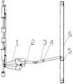
The utility model discloses a mechanical interlocking mechanism of a removable switch cabinet. The mechanical interlocking mechanism comprises a valve mechanism (1) and a circuit breaker room door (6). A guide rod (2) is fixed on the valve mechanism (1). The guide rod (2) is hinged with a connecting rod (3). The connecting rod (3) can rotate around a pin roll (4). A bending plate (5) is welded on the circuit breaker room door (6). The interlocking mechanism satisfies a requirement of a national standard GB 3906-2006. When the valve is not closed, the circuit breaker room door can be locked at a circuit breaker chamber working position. Operation personnel can be prevented from opening a compartment with the circuit breaker so that good personnel protection is achieved.
Description
Technical field
The utility model relates to a kind of interlocked operation mechanism of power distribution withdraw-type switch cabinet.
Background technology
Withdraw-type switch cabinet is a mesolow electrical power distribution system indoor complete set of equipments commonly used.In the system of rated voltage 12kV, 6kV and 3kV three-phase alternating current 50Hz, be widely used especially.Based on the explanation among the GB GB3906-2006 " the touched compartment of interlocked control "; Breaker chamber belongs to " the touched compartment of interlocked control ", requires " these compartments should be furnished with interlock and change compartment so that palp major loop parts just can be opened when not charged and ground connection or after isolated location and corresponding valve are closed ".The utility model is exactly the requirement to GB 3906-2006, withdraw-type switch cabinet is improved the interlocking that increases.
Summary of the invention
The utility model is the requirement to GB 3906-2006, and a kind of mechanical interlock mechanism of withdraw-type switch cabinet is provided, and makes circuit breaker under the situation that service position and valve are not closed, can't open the breaker chamber door, improves barrier propterty.
The technical scheme that the utility model adopts is: a kind of mechanical interlock mechanism of withdraw-type switch cabinet; Comprise valve mechanism and breaker chamber door; It is characterized in that: a fixing guide rod on valve mechanism; Guide rod is hinged with a connecting rod, and connecting rod can rotate around bearing pin, on the breaker chamber door, is welded with bent plate.
When circuit breaker when test position moves to the service position, valve is opened in the valve mechanism action, drives guide rod and connecting rod simultaneously and catches on the bent plate on the breaker chamber door, the breaker chamber door is lockable; When circuit breaker moves to test position from the service position, valve is closed in the valve mechanism action, drives guide rod and connecting rod and removes from breaker chamber door bent plate position, and the breaker chamber door can be opened.
The utility model withdraw-type switch cabinet mechanical interlock mechanism; Utilize the difference of circuit breaker in experiment position and service position; Drive the principle of valve mechanism action, on valve mechanism, increase some necessary mechanical parts, form an interlock connection with the breaker chamber door; Thereby when realizing opening the breaker chamber door, circuit breaker is in the experiment position and valve mechanism is closed.Satisfy the requirement of GB GB 3906-2006, better to personnel protection, in the breaker chamber service position and valve can pin the breaker chamber door when not closed, prevent that operating personnel from opening the belt fuser compartment.
Description of drawings
Fig. 1 is the structural representation of the utility model withdraw-type switch cabinet mechanical interlocking machine mechanism circuit-breaker when the experiment position;
Fig. 2 is the structural representation of the utility model withdraw-type switch cabinet mechanical interlocking machine mechanism circuit-breaker when the service position.
Embodiment
Below in conjunction with accompanying drawing the utility model is described further.
Among the figure: 1, valve mechanism 2, guide rod 3, connecting rod 4, bearing pin 5, bent plate 6, breaker chamber door
Shown in figure; The utility model withdraw-type switch cabinet mechanical interlock mechanism comprises valve mechanism 1 and breaker chamber door 6; A fixing guide rod 2 on valve mechanism 1, guide rod 2 can be along with valve mechanism moves, and guide rod 2 is hinged with a connecting rod 3; Connecting rod 3 can be welded with bent plate 5 around bearing pin 4 rotations on breaker chamber door 6.
When circuit breaker is in the service position, valve mechanism 1 action, guide rod 2 is with valve mechanism 1 action, and drivening rod 3 rotates, and connecting rod 3 blocks bent plate 5, pins breaker chamber door 6, and as shown in Figure 2, breaker chamber door 6 can't be opened under this state, realizes interlock.
Claims (1)
1. the mechanical interlock mechanism of a withdraw-type switch cabinet is characterized in that: go up a fixing guide rod (2) at valve mechanism (1), guide rod (2) is hinged with a connecting rod (3), and connecting rod (3) can be welded with bent plate (5) around bearing pin (4) rotation on breaker chamber door (6).
Priority Applications (1)
| Application Number | Priority Date | Filing Date | Title |
|---|---|---|---|
| CN2012200753093U CN202524002U (en) | 2012-03-02 | 2012-03-02 | Mechanical interlocking mechanism of removable switch cabinet |
Applications Claiming Priority (1)
| Application Number | Priority Date | Filing Date | Title |
|---|---|---|---|
| CN2012200753093U CN202524002U (en) | 2012-03-02 | 2012-03-02 | Mechanical interlocking mechanism of removable switch cabinet |
Publications (1)
| Publication Number | Publication Date |
|---|---|
| CN202524002U true CN202524002U (en) | 2012-11-07 |
Family
ID=47106932
Family Applications (1)
| Application Number | Title | Priority Date | Filing Date |
|---|---|---|---|
| CN2012200753093U Expired - Fee Related CN202524002U (en) | 2012-03-02 | 2012-03-02 | Mechanical interlocking mechanism of removable switch cabinet |
Country Status (1)
| Country | Link |
|---|---|
| CN (1) | CN202524002U (en) |
Cited By (3)
| Publication number | Priority date | Publication date | Assignee | Title |
|---|---|---|---|---|
| CN103050901A (en) * | 2013-01-06 | 2013-04-17 | 杭州恒信电气有限公司 | Locking devices of valves in armoured movable-type metal-enclosed switchgear |
| CN103227429A (en) * | 2013-04-23 | 2013-07-31 | 镇江大全伊顿电器有限公司 | Door locking mechanism of high-voltage switch cabinet |
| CN105932584A (en) * | 2016-07-13 | 2016-09-07 | 国网江苏省电力公司盐城供电公司 | Power supply safety device with isolation rod |
-
2012
- 2012-03-02 CN CN2012200753093U patent/CN202524002U/en not_active Expired - Fee Related
Cited By (4)
| Publication number | Priority date | Publication date | Assignee | Title |
|---|---|---|---|---|
| CN103050901A (en) * | 2013-01-06 | 2013-04-17 | 杭州恒信电气有限公司 | Locking devices of valves in armoured movable-type metal-enclosed switchgear |
| CN103050901B (en) * | 2013-01-06 | 2014-12-03 | 杭州恒信电气有限公司 | Locking devices of valves in armoured movable-type metal-enclosed switchgear |
| CN103227429A (en) * | 2013-04-23 | 2013-07-31 | 镇江大全伊顿电器有限公司 | Door locking mechanism of high-voltage switch cabinet |
| CN105932584A (en) * | 2016-07-13 | 2016-09-07 | 国网江苏省电力公司盐城供电公司 | Power supply safety device with isolation rod |
Similar Documents
| Publication | Publication Date | Title |
|---|---|---|
| CN203039283U (en) | Locking mechanism for earthing switch of switch cabinet | |
| CN204464835U (en) | A kind of cabinet door interlocking device of switch cabinet | |
| CN204632628U (en) | For the interlock of breaker main shaft in high-tension switch cabinet and isolated operation axle | |
| CN202524002U (en) | Mechanical interlocking mechanism of removable switch cabinet | |
| CN107912010B (en) | A kind of anti-interference power equipment based on shielded layer principle | |
| CN102983522A (en) | Drawer interlocking mechanism | |
| CN103489696A (en) | 10kV box type double-break vacuum circuit beaker of built-in disconnector structure | |
| CN203491181U (en) | 10kV box-type double-break vacuum circuit breaker structure with built-in isolation switch | |
| CN202183317U (en) | Interlocking device of high voltage cabinet chamber and transformer chamber in box type transformer station | |
| CN204668758U (en) | A kind of High-low voltage switch cabinet | |
| CN106532549A (en) | Hermetically sealed touch switch cabinet based on permanent magnet operating mechanism | |
| CN201877341U (en) | Interlocking device of ground switch operating mechanism | |
| CN101908424B (en) | Anti-locking mechanism of switch apparatus | |
| CN201478729U (en) | Indoor box-type metal enclosed ring main unit | |
| CN107507716B (en) | A kind of looped network cabinet switch interlock | |
| CN203895345U (en) | Solid-insulated ring main unit grounding switch locking device | |
| CN202772028U (en) | High-voltage power distribution cabinet maintenance back door electrical lockout circuit | |
| CN202333565U (en) | Chassis vehicle device with door-closing operation | |
| CN202332627U (en) | Interlocking device for preventing on-load switching-on and switching-off isolation | |
| CN203039278U (en) | Low voltage drawer cabinet live-line operation switch misoperation prevention interlocking device | |
| CN201860057U (en) | Circuit control device of low voltage distribution cabinet | |
| CN206878365U (en) | A kind of switch cubicle false-touch prevention blocking device | |
| CN201918768U (en) | Mobile phone-charging cabinet | |
| CN201708443U (en) | PT cabinet for railway 10kV power distribution | |
| CN204230682U (en) | A kind of modular ac metal closing switch gear |
Legal Events
| Date | Code | Title | Description |
|---|---|---|---|
| C14 | Grant of patent or utility model | ||
| GR01 | Patent grant | ||
| CF01 | Termination of patent right due to non-payment of annual fee |
Granted publication date: 20121107 Termination date: 20160302 |
|
| CF01 | Termination of patent right due to non-payment of annual fee |