CN202502265U - Rubber-covered cable optical fiber stripping knife - Google Patents
Rubber-covered cable optical fiber stripping knife Download PDFInfo
- Publication number
- CN202502265U CN202502265U CN2012200086687U CN201220008668U CN202502265U CN 202502265 U CN202502265 U CN 202502265U CN 2012200086687 U CN2012200086687 U CN 2012200086687U CN 201220008668 U CN201220008668 U CN 201220008668U CN 202502265 U CN202502265 U CN 202502265U
- Authority
- CN
- China
- Prior art keywords
- optical fiber
- handle
- stripping knife
- reference block
- groove
- Prior art date
- Legal status (The legal status is an assumption and is not a legal conclusion. Google has not performed a legal analysis and makes no representation as to the accuracy of the status listed.)
- Expired - Lifetime
Links
Images


Classifications
-
- G—PHYSICS
- G02—OPTICS
- G02B—OPTICAL ELEMENTS, SYSTEMS OR APPARATUS
- G02B6/00—Light guides; Structural details of arrangements comprising light guides and other optical elements, e.g. couplings
- G02B6/24—Coupling light guides
- G02B6/245—Removing protective coverings of light guides before coupling
-
- B—PERFORMING OPERATIONS; TRANSPORTING
- B26—HAND CUTTING TOOLS; CUTTING; SEVERING
- B26B—HAND-HELD CUTTING TOOLS NOT OTHERWISE PROVIDED FOR
- B26B27/00—Hand cutting tools not provided for in the preceding groups, e.g. finger rings for cutting string, devices for cutting by means of wires
-
- H—ELECTRICITY
- H02—GENERATION; CONVERSION OR DISTRIBUTION OF ELECTRIC POWER
- H02G—INSTALLATION OF ELECTRIC CABLES OR LINES, OR OF COMBINED OPTICAL AND ELECTRIC CABLES OR LINES
- H02G1/00—Methods or apparatus specially adapted for installing, maintaining, repairing or dismantling electric cables or lines
- H02G1/12—Methods or apparatus specially adapted for installing, maintaining, repairing or dismantling electric cables or lines for removing insulation or armouring from cables, e.g. from the end thereof
- H02G1/1202—Methods or apparatus specially adapted for installing, maintaining, repairing or dismantling electric cables or lines for removing insulation or armouring from cables, e.g. from the end thereof by cutting and withdrawing insulation
- H02G1/1204—Hand-held tools
- H02G1/1207—Hand-held tools the cutting element not rotating about the wire or cable
- H02G1/1209—Hand-held tools the cutting element not rotating about the wire or cable making a transverse cut
Landscapes
- Physics & Mathematics (AREA)
- Life Sciences & Earth Sciences (AREA)
- Forests & Forestry (AREA)
- Engineering & Computer Science (AREA)
- Mechanical Engineering (AREA)
- General Physics & Mathematics (AREA)
- Optics & Photonics (AREA)
- Light Guides In General And Applications Therefor (AREA)
- Removal Of Insulation Or Armoring From Wires Or Cables (AREA)
Abstract
一种皮线缆光纤(又称FTTH光纤,以下皆称皮线缆光纤)剥刀,包括手柄、二块剥刀和光纤定位基准块,二块剥刀通过刀片转轴分别活动设在手柄上,二块剥刀呈剪切状设置,手柄通过手柄转轴与光纤定位基准块活动连接,光纤定位基准块上设有方形槽和V形槽,剥刀上设有方形开口和V形开口,剥刀上的方形开口与基准块上的方形槽对应,手柄上还设有长度定位尺和可调螺钉,通过可调螺钉可调整手柄的运动行程,本实用新型能保证切剥光纤时光纤不会断裂,并能防止光纤表面附着上杂物,大大提高了光纤熔接效率。
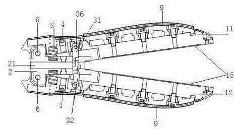
A leather cable optical fiber (also known as FTTH optical fiber, hereinafter referred to as leather cable optical fiber) stripping knife, including a handle, two stripping knives and an optical fiber positioning reference block, the two stripping knives are respectively movable on the handle through the blade rotating shaft, The two stripping knives are arranged in a shearing shape, and the handle is movably connected with the optical fiber positioning reference block through the handle shaft. The optical fiber positioning reference block is provided with a square groove and a V-shaped groove, and the stripping knife is provided with a square opening and a V-shaped opening. The square opening on the top corresponds to the square groove on the reference block. The handle is also equipped with a length positioning ruler and an adjustable screw. The movement stroke of the handle can be adjusted through the adjustable screw. The utility model can ensure that the optical fiber will not be broken when cutting and stripping the optical fiber. , and can prevent impurities from attaching to the surface of the optical fiber, greatly improving the efficiency of optical fiber fusion.
Description
技术领域 technical field
本实用新型涉及线缆剥除外皮的剥刀,特别是一种皮线缆光纤剥刀。 The utility model relates to a stripping knife for stripping the outer sheath of cables, in particular to a stripping knife for sheathed cables and optical fibers. the
背景技术 Background technique
现有的光纤或是电缆在剥除纯缘外皮时,使用的是各种钳子或其他手动工具,为了确保电线在去除绝缘层时不受损坏,并且还要确保线缆剥除的干净,传统的剥线钳利用钳口上的刀刃切开绝缘层,然后拉线缆将绝缘层剥离,另外,不同的线缆采用不同的刃口,操作不当会损害光纤,现有一种用于线缆绝缘层的钳的,利用一对外部夹持钳口和一对内部剪切钳口,在线缆直径小的情况下,夹持配合不好容易将光纤剪断,和去皮不干净的情况。 When the existing optical fiber or cable is stripped of the sheath, various pliers or other manual tools are used. In order to ensure that the wire is not damaged when the insulation layer is removed, and to ensure that the cable is stripped cleanly, the traditional The wire stripper uses the blade on the jaws to cut the insulation layer, and then pulls the cable to peel off the insulation layer. In addition, different cables use different cutting edges, and improper operation will damage the optical fiber. There is an existing one for the cable insulation layer. The pliers use a pair of external clamping jaws and a pair of internal cutting jaws. When the diameter of the cable is small, it is easy to cut the optical fiber if the clamping fit is not good, and the peeling is not clean. the
还有一种剥线钳,具有两对可回转支承的钳口,其中外部一对钳口作为夹持钳口构成和另一对人部钳口作为具有切入绝缘内剪切刀的剪切口构成,通过一个偏心轮可与不同的线缆横截面和绝缘层厚度配合,操作者可通过偏心轮的扭转改变下部剪切口的位置。 There is also a wire stripper with two pairs of rotatably supported jaws, wherein the outer pair of jaws is formed as a clamping jaw and the other pair of human jaws is formed as a shear with a shear knife cut into the insulation. , Through an eccentric wheel, it can be matched with different cable cross-sections and insulation layer thicknesses, and the operator can change the position of the lower cutout by twisting the eccentric wheel. the
上述剥钳使用虽然方便了许多,但是不能很好的解决光纤断裂或表面附着杂物的问题,给光纤施工增加难度,造成熔接损耗大,施工效率低。 Although the use of the above stripping pliers is much more convenient, it cannot solve the problem of fiber breakage or surface attachment of debris, which increases the difficulty of optical fiber construction, resulting in large fusion splice loss and low construction efficiency. the
实用新型内容 Utility model content
一种皮线缆光纤剥刀,包括第一手柄、第二手柄、第一剥刀、第二剥刀和光纤定位基准块,第一手柄和第二手柄上分别设有长槽,第一剥刀通过刀片转轴安装在第一手柄的长槽内,第二剥刀通过刀片转轴安装在第二手柄的长槽内,第一手柄和第二手柄分别通过手柄转轴与光纤基准块活动连接,第一剥刀和第二剥刀刀刃呈剪切方向设置。 A skin cable optical fiber stripper, comprising a first handle, a second handle, a first stripper, a second stripper and an optical fiber positioning reference block, the first handle and the second handle are respectively provided with long grooves, the first stripper The knife is installed in the long groove of the first handle through the blade rotating shaft, and the second stripping knife is installed in the long groove of the second handle through the blade rotating shaft. The first handle and the second handle are respectively connected to the optical fiber reference block through the handle rotating shaft. The blades of the first stripping knife and the second stripping knife are arranged in a shearing direction. the
所述第一手柄和第二手柄内设有长度定位尺和调节螺钉。 The first handle and the second handle are provided with a length positioning ruler and an adjusting screw. the
所述第一剥刀和第二剥刀上分别设有方形开口和尖角开口,方形开口与尖角形开口底部设有刀刃 ,方形开口底部的中间位置开有第一小槽,尖角开口的尖角处设有第二小槽,第一小槽和第二小槽可分别保证裸纤通过无损伤和去除裸纤涂层的纤芯通过无损伤。 The first stripping knife and the second stripping knife are respectively provided with a square opening and a sharp corner opening, the bottom of the square opening and the sharp corner opening is provided with a blade, the middle position of the bottom of the square opening is provided with a first small groove, and the sharp corner opening A second small groove is provided at the sharp corner, and the first small groove and the second small groove can respectively ensure that the bare fiber passes through without damage and the fiber core with the bare fiber coating removed passes through without damage. the
所述光纤定位基准块上设有若干个槽口和刀片定位导向槽,所述槽口包括方形槽和V形槽,刀片定位导向槽贯穿整个光纤定位基准块,并与方形槽和V形槽连通,第一剥刀和第二剥刀分别设在刀片定位导向槽的两侧,剥刀的方形开口与光纤定位基准块上的方形槽对应,剥刀的尖角开口和V形槽对应。 The optical fiber positioning reference block is provided with several notches and blade positioning guide grooves. The notches include square grooves and V-shaped grooves. The blade positioning guide grooves run through the entire optical fiber positioning reference block, and are connected with the square grooves and V-shaped grooves. Connected, the first stripping knife and the second stripping knife are respectively arranged on both sides of the blade positioning guide groove, the square opening of the stripping knife corresponds to the square groove on the optical fiber positioning reference block, and the sharp corner opening of the stripping knife corresponds to the V-shaped groove. the
所述光纤定位基准块上装有顶块销。 The fiber positioning reference block is equipped with jacking pins. the
所述第一手柄和第二手柄与光纤定位基准块之间分别设有弹簧。 Springs are respectively arranged between the first handle, the second handle and the optical fiber positioning reference block. the
所述第一手柄和第二手柄的外侧分别设有橡胶握柄。 The outer sides of the first handle and the second handle are respectively provided with rubber handles. the
本实用新型利用呈剪切方向设置的第一剥刀和第二剥刀将外皮剥离,调节可调螺钉,就可改变第一手柄与第二手柄握紧时与光纤定位基准块之间的角度,从而改变刀片的剪切行程并且利用可调螺钉来调整手柄的行程使剥刀在剥纤时不会伤到光纤,剥刀上还设有小槽,使本剥刀不仅能剥皮缆还能剥去裸纤涂层,手柄上还设有长度定位尺,可使剥的线缆长度更准确不浪费。 The utility model uses the first stripping knife and the second stripping knife set in the shearing direction to peel off the outer skin, and adjusts the adjustable screw to change the angle between the first handle and the second handle and the optical fiber positioning reference block when they are gripped tightly. , so as to change the cutting stroke of the blade and use the adjustable screw to adjust the stroke of the handle so that the stripping knife will not damage the optical fiber when stripping the fiber. There is also a small groove on the stripping knife, so that the stripping knife can not only strip the cable but also Strip the bare fiber coating, and there is also a length positioning ruler on the handle, which can make the length of the stripped cable more accurate and waste less. the
还有,剥刀的方形开口和V形开口的底部都设有小槽,使本实用新型剥刀不仅能快速干净的剥纤,还能利用长度定位尺准确的定位裸纤的长度。 In addition, the bottom of the square opening and the V-shaped opening of the stripping knife are provided with small grooves, so that the stripping knife of the utility model can not only strip the fiber quickly and cleanly, but also use the length positioning ruler to accurately locate the length of the bare fiber. the
本实用新型能保证切剥光纤时光纤不会断裂,并能防止光纤表面附着上杂物,大大提高了光纤熔接效率。 The utility model can ensure that the optical fiber will not be broken when the optical fiber is cut and stripped, and can prevent impurities from adhering to the surface of the optical fiber, thereby greatly improving the efficiency of optical fiber fusion splicing. the
本实用新型还设有方形槽和V形槽,通过方形槽和V形槽可分别切开光纤的外皮和裸纤涂层,还能精确的定位裸纤的长度,精度高,使用方便。 The utility model is also provided with a square groove and a V-shaped groove, through which the skin of the optical fiber and the coating of the bare fiber can be cut respectively, and the length of the bare fiber can be accurately positioned, with high precision and convenient use. the
附图说明 Description of drawings
图1为本实用新型皮线缆光纤剥刀的示意图; Fig. 1 is the schematic diagram of the utility model leather cable optical fiber stripping knife;
图2为本实用新型皮线缆光纤剥刀的另一示意图; Fig. 2 is another schematic diagram of the utility model leather cable optical fiber stripper;
图3为本实用新型光纤定位基准块的示意图; Fig. 3 is the schematic diagram of the utility model optical fiber positioning reference block;
图4为本实用新型光纤定位基准块的另一示意图; Fig. 4 is another schematic diagram of the optical fiber positioning reference block of the present invention;
图5为本实用新型剥刀的示意图; Fig. 5 is the schematic diagram of the utility model stripping knife;
图6为本实用新型剥刀剪切时的部分示意图。 Fig. 6 is a partial schematic diagram of the utility model when the stripping knife is shearing. the
具体实施方式 Detailed ways
下面参照附图来进一步说明本实用新型。 Further illustrate the utility model below with reference to accompanying drawing. the
一种皮线缆光纤剥刀,包括第一手柄11、第二手柄12、第一剥刀31、第二剥刀32和光纤定位基准块2,第一剥刀31通过刀片转轴36安装在第一手柄11的长槽13内,第二剥刀32通过刀片转轴36安装在第二手柄12的长槽14内,第一手柄11和第二手柄12分别通过手柄转轴6与光纤基准块2活动连接,第一手柄11和第二手柄12内设有长度定位尺15和调节螺钉4,第一剥刀31和第二剥刀32上分别设有方形开口33和尖角开口34,方形开口33底部的中间位置开有第一小槽331,尖角开口34的尖角处设有第二小槽341,方形开口33、尖角开口34、方形开口与尖角形开口底部设有刀刃35,第一剥刀31和第二剥刀32的刀刃35呈剪切方向设置,光纤定位基准块2上设有方形槽21和V形槽22,同时还设有刀片定位导向槽23,刀片定位导向槽23贯穿整个光纤定位基准块2并与方形槽21和V形槽22连通,第一剥刀31和第二剥刀32分别设在刀片定位导向槽23的两侧,第一剥刀31和第二剥刀32的方形开口33与光纤定位基准块上的方形槽21对应,尖角开口34和V形槽22对应,光纤定位基准块2上装有顶块销5,第一手柄11和第二手柄12的可调螺钉1分别顶在其对应一侧的顶块销上,第一手柄11和第二手柄12与光纤定位基准块2之间分别设有弹簧8,弹簧8使第一手柄11和第二手柄12处于张开状态,第一手柄11和第二手柄12的外侧分别设有橡胶握柄9。
A skin cable optical fiber stripping knife, including a
旋转可调螺钉4,以此来确定第一剥刀31和第二剥刀32切入线缆的深度,确保能刚好切开皮缆而不会损伤到光纤。将皮线缆从皮线缆光纤剥刀头部的方形槽21插入,放置需要的长度,在长度定位尺15上测定需要的长度,握紧手柄,第一剥刀31和第二剥刀32从刀片定位导向槽23的两端向皮线缆处合拢,刀刃35将皮线缆的表皮切开,再将皮线缆从反方向拉出就可将表皮剥开。同样,将剥去皮线缆表皮的的裸纤放置在光纤定位基准块的V槽处,用光纤定位基准块上V槽根部的方形开口槽定位,然后握紧手柄,让第一剥刀31和第二剥刀32从刀片定位导向槽23的两端向内合拢,再纵向拉动皮线缆剥刀就可将裸纤的光纤涂层去除。
Rotate the adjustable screw 4 to determine the cutting depth of the
上述公开的仅为本实用新型的具体实施例,该实施例只为更清楚的说明本实用新型所用,而并非对本实用新型的限定,任何本领域的技术人员能思之的变化,都应落在保护范围内。 The above disclosure is only a specific embodiment of the utility model, which is only used to illustrate the utility model more clearly, but not to limit the utility model. Any changes that those skilled in the art can think of should fall into the within the scope of protection. the
Claims (7)
Priority Applications (4)
| Application Number | Priority Date | Filing Date | Title |
|---|---|---|---|
| CN2012200086687U CN202502265U (en) | 2012-01-10 | 2012-01-10 | Rubber-covered cable optical fiber stripping knife |
| KR2020147000036U KR200480900Y1 (en) | 2012-01-10 | 2012-05-18 | Stripper for stripping cladded optical fibre cables |
| PCT/CN2012/075737 WO2013104166A1 (en) | 2012-01-10 | 2012-05-18 | Stripper for stripping cladded optical fibre cables |
| US14/279,772 US9958610B2 (en) | 2012-01-10 | 2014-05-16 | Optical fiber stripper |
Applications Claiming Priority (1)
| Application Number | Priority Date | Filing Date | Title |
|---|---|---|---|
| CN2012200086687U CN202502265U (en) | 2012-01-10 | 2012-01-10 | Rubber-covered cable optical fiber stripping knife |
Publications (1)
| Publication Number | Publication Date |
|---|---|
| CN202502265U true CN202502265U (en) | 2012-10-24 |
Family
ID=47038875
Family Applications (1)
| Application Number | Title | Priority Date | Filing Date |
|---|---|---|---|
| CN2012200086687U Expired - Lifetime CN202502265U (en) | 2012-01-10 | 2012-01-10 | Rubber-covered cable optical fiber stripping knife |
Country Status (4)
| Country | Link |
|---|---|
| US (1) | US9958610B2 (en) |
| KR (1) | KR200480900Y1 (en) |
| CN (1) | CN202502265U (en) |
| WO (1) | WO2013104166A1 (en) |
Cited By (5)
| Publication number | Priority date | Publication date | Assignee | Title |
|---|---|---|---|---|
| CN103995316A (en) * | 2014-04-18 | 2014-08-20 | 烽火通信科技股份有限公司 | Optical cable sheath layer window stripping device |
| CN104459888A (en) * | 2014-11-26 | 2015-03-25 | 江西大圣塑料光纤有限公司 | Special shear for plastic optical fiber |
| CN105511018A (en) * | 2016-01-12 | 2016-04-20 | 东莞市翔通光电技术有限公司 | A non-destructive fiber stripping method |
| CN110676767A (en) * | 2019-09-10 | 2020-01-10 | 国网内蒙古东部电力有限公司 | Automatic peeler |
| CN110707609A (en) * | 2019-09-10 | 2020-01-17 | 合肥中科蓝睿科技有限公司 | A peeling fixture with zero reference adjustment function |
Families Citing this family (11)
| Publication number | Priority date | Publication date | Assignee | Title |
|---|---|---|---|---|
| WO2014019280A1 (en) * | 2012-08-03 | 2014-02-06 | 大豪信息技术(威海)有限公司 | Hot melt connector stripping cutting tool |
| WO2015081885A1 (en) * | 2013-12-06 | 2015-06-11 | Tyco Electronics Raychem Bvba | Tool for preparing a cable for termination |
| CN104238015B (en) * | 2014-09-15 | 2017-05-24 | 成都奥捷通信技术有限公司 | Hot stripping pliers for optical cable |
| US10279384B2 (en) | 2015-07-23 | 2019-05-07 | Ford Motor Company | Device for scraping debris from metal wire |
| US10234631B2 (en) | 2015-12-14 | 2019-03-19 | Ofs Fitel, Llc | Preventing delamination of a coating on an optical fiber when stripping the fiber |
| USD796926S1 (en) * | 2016-03-31 | 2017-09-12 | Inno Instrument (China) Inc. | Ribbon fiber optic thermal stripper |
| US10761269B2 (en) * | 2016-07-29 | 2020-09-01 | Commscope Technologies Llc | Thermal flash conditioner for fusion splicing; and methods |
| KR101858707B1 (en) * | 2016-09-28 | 2018-05-16 | 이상식 | Cutting device of optical cable |
| US11513290B2 (en) * | 2019-08-30 | 2022-11-29 | Commscope Technologies Llc | Strip stop mechanism using rotating lever as a positioning stop |
| CN113900203B (en) * | 2021-10-25 | 2022-11-18 | 长飞光纤光缆股份有限公司 | Sleeve single-side opening device |
| JP1762909S (en) * | 2023-04-25 | 2024-02-05 | Optical fiber sheath remover |
Family Cites Families (11)
| Publication number | Priority date | Publication date | Assignee | Title |
|---|---|---|---|---|
| US3939552A (en) * | 1974-11-26 | 1976-02-24 | Amp Incorporated | Method and apparatus for feeding a pair of wires |
| US4271729A (en) * | 1979-02-16 | 1981-06-09 | Micro Electronics, Inc. | Wire stripping device |
| KR200314261Y1 (en) | 2003-02-27 | 2003-05-23 | 한국티엠씨 주식회사 | Buffer Stripping Apparatus for Optical Cable |
| US20050044715A1 (en) * | 2003-08-25 | 2005-03-03 | Connectool Inc. | Stripping tool for fiber optic cables |
| JP2006030579A (en) | 2004-07-15 | 2006-02-02 | Sumitomo Electric Ind Ltd | Optical fiber cable extraction tool and extraction method using this tool |
| US20060265881A1 (en) | 2005-05-31 | 2006-11-30 | Serrano Jorge R | Stripping device with alignment maintaining feature for improving strip performance |
| JP2007171419A (en) * | 2005-12-20 | 2007-07-05 | Occ Corp | Tool for branching optical fiber tape |
| CN201266262Y (en) * | 2008-09-02 | 2009-07-01 | 江苏宇特光电科技有限公司 | Device for peeling optical cable |
| US8640329B2 (en) * | 2008-09-03 | 2014-02-04 | Adc Telecommunications, Inc. | Hybrid fiber/copper cable preparation tool |
| CN201812078U (en) * | 2010-09-20 | 2011-04-27 | 徐伟 | Multifunctional optical cable stripper |
| CN202093202U (en) * | 2011-06-15 | 2011-12-28 | 刘荣伟 | Optical fiber coating layer fixed length stripping tool |
-
2012
- 2012-01-10 CN CN2012200086687U patent/CN202502265U/en not_active Expired - Lifetime
- 2012-05-18 WO PCT/CN2012/075737 patent/WO2013104166A1/en not_active Ceased
- 2012-05-18 KR KR2020147000036U patent/KR200480900Y1/en not_active Expired - Fee Related
-
2014
- 2014-05-16 US US14/279,772 patent/US9958610B2/en active Active
Cited By (7)
| Publication number | Priority date | Publication date | Assignee | Title |
|---|---|---|---|---|
| CN103995316A (en) * | 2014-04-18 | 2014-08-20 | 烽火通信科技股份有限公司 | Optical cable sheath layer window stripping device |
| CN103995316B (en) * | 2014-04-18 | 2016-09-07 | 烽火通信科技股份有限公司 | Cable jacket layer window stripping apparatus |
| CN104459888A (en) * | 2014-11-26 | 2015-03-25 | 江西大圣塑料光纤有限公司 | Special shear for plastic optical fiber |
| CN104459888B (en) * | 2014-11-26 | 2017-05-10 | 江西大圣塑料光纤有限公司 | Special shear for plastic optical fiber |
| CN105511018A (en) * | 2016-01-12 | 2016-04-20 | 东莞市翔通光电技术有限公司 | A non-destructive fiber stripping method |
| CN110676767A (en) * | 2019-09-10 | 2020-01-10 | 国网内蒙古东部电力有限公司 | Automatic peeler |
| CN110707609A (en) * | 2019-09-10 | 2020-01-17 | 合肥中科蓝睿科技有限公司 | A peeling fixture with zero reference adjustment function |
Also Published As
| Publication number | Publication date |
|---|---|
| KR200480900Y1 (en) | 2016-07-20 |
| WO2013104166A1 (en) | 2013-07-18 |
| KR20140004960U (en) | 2014-09-15 |
| US9958610B2 (en) | 2018-05-01 |
| US20140338195A1 (en) | 2014-11-20 |
Similar Documents
| Publication | Publication Date | Title |
|---|---|---|
| CN201708483U (en) | Power cable stripper | |
| CN205123152U (en) | Cable pliers of skinning | |
| WO2013104166A1 (en) | Stripper for stripping cladded optical fibre cables | |
| CN205581343U (en) | Flexibility is shelled to press from both sides and is cut fiber -optic device | |
| CN201742038U (en) | Cable stripping knife | |
| CN205104851U (en) | Control cable wire stripping pliers | |
| CN208438227U (en) | Wire stripper | |
| CN102801119A (en) | Signal-cable stripping forceps | |
| CN209088422U (en) | A kind of auxiliary tool of conducting wire skin stripping | |
| WO2021051235A1 (en) | Multipurpose optical fiber stripping pliers | |
| CN110459990A (en) | a wire stripper | |
| CN209516486U (en) | For removing the manual wire stripper of wire outer skin | |
| CN201174541Y (en) | cable stripper | |
| CN103928875B (en) | Cable skin wire stripper | |
| CN204668847U (en) | A cable stripping device | |
| CN206531994U (en) | Optical cable laterally drives cable instrument | |
| CN205539567U (en) | Multi -thread optic fibre heat strips ware | |
| CN216622758U (en) | Fixed-length stripping pliers for sheath of multi-core optical cable | |
| CN205666559U (en) | Electric power multi -core control cable crust cutterbar | |
| CN203800498U (en) | Cable skin stripper | |
| CN210007264U (en) | a wire stripper | |
| CN202424029U (en) | High-stability cable longitudinal stripping knife | |
| CN102611044A (en) | Control cable stripper | |
| CN212399285U (en) | Integrative pincers of trimming wire stripping | |
| CN210379745U (en) | Cable stripping device |
Legal Events
| Date | Code | Title | Description |
|---|---|---|---|
| C14 | Grant of patent or utility model | ||
| GR01 | Patent grant | ||
| C56 | Change in the name or address of the patentee |
Owner name: INNOINSTRUMENT (WEIHAI) CO., LTD. Free format text: FORMER NAME: INNO INSTRUMENT (WEIHAI) CO., LTD. |
|
| CP03 | Change of name, title or address |
Address after: 264200 Shandong city of Weihai province Weihai Dalian District Road No. 71 Patentee after: DH INFOTECH (WEIHAI) Inc. Address before: 264207 Shandong city of Weihai province Weihai Dalian District Road No. 71 Patentee before: INNO INSTRUMENT (WEI HAI) Inc. |
|
| C56 | Change in the name or address of the patentee | ||
| CP01 | Change in the name or title of a patent holder |
Address after: 264200 Weihai high tech Zone, Tianjin, No. 190 Shandong Road Hospital Patentee after: INNO INSTRUMENT (CHINA). Inc. Address before: 264200 Weihai high tech Zone, Tianjin, No. 190 Shandong Road Hospital Patentee before: INNO INSTRUMENT (WEI HAI) Inc. |
|
| CP03 | Change of name, title or address |
Address after: 264200 Weihai high tech Zone, Tianjin, No. 190 Shandong Road Hospital Patentee after: INNO INSTRUMENT (WEI HAI) Inc. Address before: 264200 Shandong city of Weihai province Weihai Dalian District Road No. 71 Patentee before: DH INFOTECH (WEIHAI) Inc. |
|
| CX01 | Expiry of patent term | ||
| CX01 | Expiry of patent term |
Granted publication date: 20121024 |