CN202498849U - End cam upward pressing mechanism of plastic pipe binding machine - Google Patents
End cam upward pressing mechanism of plastic pipe binding machine Download PDFInfo
- Publication number
- CN202498849U CN202498849U CN2012201267406U CN201220126740U CN202498849U CN 202498849 U CN202498849 U CN 202498849U CN 2012201267406 U CN2012201267406 U CN 2012201267406U CN 201220126740 U CN201220126740 U CN 201220126740U CN 202498849 U CN202498849 U CN 202498849U
- Authority
- CN
- China
- Prior art keywords
- bearing
- rotating shaft
- end cam
- edge cam
- pedestal
- Prior art date
- Legal status (The legal status is an assumption and is not a legal conclusion. Google has not performed a legal analysis and makes no representation as to the accuracy of the status listed.)
- Expired - Fee Related
Links
- 238000003825 pressing Methods 0.000 title abstract description 7
- NJPPVKZQTLUDBO-UHFFFAOYSA-N novaluron Chemical compound C1=C(Cl)C(OC(F)(F)C(OC(F)(F)F)F)=CC=C1NC(=O)NC(=O)C1=C(F)C=CC=C1F NJPPVKZQTLUDBO-UHFFFAOYSA-N 0.000 claims description 15
- 239000011230 binding agent Substances 0.000 claims description 12
- 230000006835 compression Effects 0.000 claims description 10
- 238000007906 compression Methods 0.000 claims description 10
- -1 cam Chemical compound 0.000 claims description 3
- 238000007731 hot pressing Methods 0.000 abstract 3
- 238000000465 moulding Methods 0.000 description 3
- 206010053615 Thermal burn Diseases 0.000 description 2
- 230000002950 deficient Effects 0.000 description 1
- 238000005516 engineering process Methods 0.000 description 1
- 238000000034 method Methods 0.000 description 1
Images
Landscapes
- Gears, Cams (AREA)
Abstract
The utility model relates to an end cam upward pressing mechanism of a plastic pipe binding machine. The mechanism comprises a base, an end cam, a rotating shaft and a bearing, wherein a hole for holding the bearing is arranged on the base; the end cam is arranged on the base via the rotating shaft; and one end of the rotating shaft is inserted in the bearing. The mechanism is characterized in that an elastic support device for supporting the bearing is also arranged at the lower end of the bearing. According to the technical scheme, the end cam upward pressing mechanism of the plastic pipe binding machine can prevent upper hot-pressing heads from enduring too high pressure, thus preventing deformation of the upper hot-pressing heads; and the mechanism can provide enough pressing forces when hot pressing is performed on thinner account books.
Description
Technical field
The utility model relates to the pipe binder field of moulding, press mechanism on particularly a kind of edge cam of moulding the pipe binder.
Background technology
Mould the pipe binder edge cam on press mechanism be to mould the pipe important component part in the indexing mechanism of perming under the binder, its be mainly used in that driving perms down and rise with on perm to pressure.
At present, existing mould the pipe binder edge cam on press mechanism include pedestal, edge cam, gear wheel, rotating shaft, bearing; Edge cam, gear wheel are arranged on the pedestal through rotating shaft, and pedestal is provided with dead eye, and bearing is arranged in the dead eye; Be provided with the shoulder rank in the dead eye, bearing is through location, shoulder rank, and rotating shaft is plugged in the bearing; Wherein, described gear wheel be used for motor output shaft on pinion, motor output shaft drives the gear wheel rotation through pinion; Thereby drive the edge cam rotation, again by the rotation of edge cam drive perm down rise with on perm to pressure.
But, press mechanism on the edge cam of this structure and since on the pressure ratio of perming bigger, the pressure of perming is down directly born by the shoulder rank, like this, causes the pressurized of perming excessive easily, produces distortion thereby perm on making, causes and moulds pipe binder fault; And, scalding when pressing for the account book class object of thinner thickness, the pressure of perming down can not be excessive, thereby make thrust not enough.
Summary of the invention
The purpose of the utility model: in order to overcome the defective of prior art, the utility model provides a kind of press mechanism on the edge cam of managing binder of moulding, and the pressurized of avoiding perming is excessive, is out of shape thereby can avoid perming producing; And, scald when pressing for the account book class object of thinner thickness, enough thrusts can be provided.
The technical scheme of the utility model: a kind of mould the pipe binder edge cam on press mechanism; Include pedestal; Edge cam, rotating shaft, bearing, pedestal are provided with the hole that is used for ccontaining bearing, and described edge cam is arranged on the pedestal through rotating shaft; Described rotating shaft one end is plugged in the bearing, it is characterized in that: described bearing lower end also is provided with the resilient supporting unit that is used for spring bearing.
Adopt technique scheme, through the resilient supporting unit that is provided with, at the last pressure of perming during greater than the compression spring force, the compression of compression spring, thus the pressurized of avoiding perming is excessive, and then can avoid perming and produce distortion; And, scald when pressing for the account book class object of thinner thickness, enough thrusts can be provided.
The further setting of the utility model: described resilient supporting unit includes compression spring, spring base; Described hole is a through hole; Described compression spring one end and spring base are conflicted, and conflict in the other end and bearing lower surface, and described spring base is fixedly connected with the pedestal lower surface.
Adopt above-mentioned further setting, the resilient supporting unit of this structure, simple in structure, spring base can be located the compression spring well.
Description of drawings
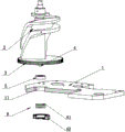
Fig. 1 is the exploded sketch of the utility model specific embodiment.
The specific embodiment
As shown in Figure 1; A kind of mould the pipe binder edge cam on press mechanism, include pedestal 1, edge cam 2, gear 3, rotating shaft 4, bearing 5; Pedestal 1 is provided with the hole 11 that is used for ccontaining bearing 5; Described edge cam 2 is arranged on the pedestal 1 through rotating shaft 4, and described rotating shaft 4 one ends are plugged in the bearing 5, and described bearing 5 lower ends also are provided with the resilient supporting unit 6 that is used for spring bearing 5.
In the utility model specific embodiment; Described resilient supporting unit 6 includes compression spring 61, spring base 62; Described hole 11 is a through hole; Described compression spring 61 1 ends and spring base 62 are conflicted, and conflict in the other end and bearing 5 lower surfaces, and described spring base 62 is fixedly connected with pedestal 1 lower surface.
Claims (2)
1. mould press mechanism on the edge cam of managing binder for one kind; Include pedestal; Edge cam, rotating shaft, bearing, pedestal are provided with the hole that is used for ccontaining bearing, and described edge cam is arranged on the pedestal through rotating shaft; Described rotating shaft one end is plugged in the bearing, it is characterized in that: described bearing lower end also is provided with the resilient supporting unit that is used for spring bearing.
2. according to claim 1 mould the pipe binder edge cam on press mechanism; It is characterized in that: described resilient supporting unit includes compression spring, spring base; Described hole is a through hole; Described compression spring one end and spring base are conflicted, and conflict in the other end and bearing lower surface, and described spring base is fixedly connected with the pedestal lower surface.
Priority Applications (1)
| Application Number | Priority Date | Filing Date | Title |
|---|---|---|---|
| CN2012201267406U CN202498849U (en) | 2012-03-29 | 2012-03-29 | End cam upward pressing mechanism of plastic pipe binding machine |
Applications Claiming Priority (1)
| Application Number | Priority Date | Filing Date | Title |
|---|---|---|---|
| CN2012201267406U CN202498849U (en) | 2012-03-29 | 2012-03-29 | End cam upward pressing mechanism of plastic pipe binding machine |
Publications (1)
| Publication Number | Publication Date |
|---|---|
| CN202498849U true CN202498849U (en) | 2012-10-24 |
Family
ID=47035474
Family Applications (1)
| Application Number | Title | Priority Date | Filing Date |
|---|---|---|---|
| CN2012201267406U Expired - Fee Related CN202498849U (en) | 2012-03-29 | 2012-03-29 | End cam upward pressing mechanism of plastic pipe binding machine |
Country Status (1)
| Country | Link |
|---|---|
| CN (1) | CN202498849U (en) |
-
2012
- 2012-03-29 CN CN2012201267406U patent/CN202498849U/en not_active Expired - Fee Related
Similar Documents
| Publication | Publication Date | Title |
|---|---|---|
| CN203994788U (en) | A kind of press fit device | |
| CN204294851U (en) | A kind of clutch lid assembly riveting die | |
| CN202498849U (en) | End cam upward pressing mechanism of plastic pipe binding machine | |
| CN101590505A (en) | A kind of automatic edge former of pressure gauge | |
| CN204270763U (en) | A kind of disc insulator cast shaping device | |
| CN202727395U (en) | Fast tableware molding machine | |
| CN202174191U (en) | Device for pressing bending parts | |
| CN203887979U (en) | Solid wood bending hot pressing forming machine | |
| CN202558587U (en) | Semi-automatic pressure gauge cover screwing machine | |
| CN206911997U (en) | A kind of leaf spring becomes bow shaped device | |
| CN207479336U (en) | Bending mould | |
| CN102610981A (en) | Positioning and press-fit composite die | |
| CN203580226U (en) | Novel heaven and earth cover forming machine center shaft assembly | |
| CN201730023U (en) | Book flat press | |
| CN202952033U (en) | Multihead camera lens punching machine | |
| CN202141880U (en) | camera focus gear | |
| CN207711291U (en) | A kind of ejecting mechanism of injection mold | |
| CN207839991U (en) | A kind of semiaxis balance shaping mould | |
| CN103273458B (en) | A kind of fan assembling device | |
| CN202985987U (en) | Slide block retreating device | |
| CN203071745U (en) | Stator shaping clamp | |
| CN203438450U (en) | Compressed air demolding device | |
| CN2809658Y (en) | Experimental bench for motor with working state simulation | |
| CN203418772U (en) | Press forming device | |
| CN104552042B (en) | Feeding, net-pressing and lifting compression ring for grinding wheel production |
Legal Events
| Date | Code | Title | Description |
|---|---|---|---|
| C14 | Grant of patent or utility model | ||
| GR01 | Patent grant | ||
| CF01 | Termination of patent right due to non-payment of annual fee | ||
| CF01 | Termination of patent right due to non-payment of annual fee |
Granted publication date: 20121024 Termination date: 20210329 |