CN202497901U - Roll surface of rolling machine - Google Patents
Roll surface of rolling machine Download PDFInfo
- Publication number
- CN202497901U CN202497901U CN2012200890584U CN201220089058U CN202497901U CN 202497901 U CN202497901 U CN 202497901U CN 2012200890584 U CN2012200890584 U CN 2012200890584U CN 201220089058 U CN201220089058 U CN 201220089058U CN 202497901 U CN202497901 U CN 202497901U
- Authority
- CN
- China
- Prior art keywords
- roll surface
- pillar
- nail
- roll
- edge
- Prior art date
- Legal status (The legal status is an assumption and is not a legal conclusion. Google has not performed a legal analysis and makes no representation as to the accuracy of the status listed.)
- Expired - Lifetime
Links
Images

Landscapes
- Reduction Rolling/Reduction Stand/Operation Of Reduction Machine (AREA)
Abstract
The utility model discloses a roll surface of a rolling machine. The roll surface comprises big studs, small studs I and small studs II uniformly and densely distributed on the roll surface in a staggered manner, wherein the small studs I are arranged on the vacancy between two big studs on the edge of the roll surface; and the small studs II are arranged on the outer edge of the roll surface. Through the roll surface of the rolling machine, the whole roll surface can get wear-resistant protection, the service life of the whole roll surface is prolonged, the manufacturing cost and maintenance cost of the roll surface are reduced, the running rate of a roller is effectively improved, and the roller edge can be reliably and effectively protected after long-term use; and by using the roll surface, the service life can be prolonged by 15%, and the manufacturing cost can be reduced by 8%.
Description
Technical field
The utility model relates to a kind of roll squeezer roll surface, relates in particular to a kind of roller roll surface that is used for industry roll-in milling equipment roll squeezers such as building material cement, metallurgical mine, coal, chemical industry, belongs to the roll squeezer technical field.
Background technology
When roll squeezer (also claiming high-pressure roller mill) roller tribulation grind materials, like slag, iron ore, quartz mine etc., the roller roll surface of roll squeezer adopts the method for tungsten carbide button's post nail to guarantee its wearability usually.But there is not effective guard method at the edge of roller always, and this makes that the service life at roller edge is more much lower than other position, and the wear-resistant protection at roller edge remains the big technological difficulties in the roller abrasionproof technology.Past; In order to protect at the pair of rollers edge, the method that adopts usually is at roller edge built-up welding one deck high-abrasive material, but adopts the service life of the roller corner that this method produces still very low; Need regular built-up welding; The number of times of repeated overlaying weldability is limited, often falls the piece phenomenon because the corner takes place weld crack, can not satisfy instructions for use.
The Chinese patent publication number is CN201586536U, and the utility model name is called " roller end face scuff-resistant coating armor " and discloses a kind of roller end face scuff-resistant coating armor, comprises roller shell, and the end face of roller shell is provided with annular groove, and correspondence is provided with abrasionproof mechanism in annular groove.Though this device can solve end wear, this method still can not be separated fast roller corner wear problem effectively; And carry out wear-resistingly with being in mushroom head on the roll surface, only provided a theoretic notion, practical implementation and operating position are made detailed explanation.
The Chinese patent publication number is CN201969585U; The utility model name is called " roller of a kind of band edge angle protection " and discloses a kind of method that adopts gusset or protruding wear-resistant block pair of rollers edge to carry out the abrasionproof protection; Change after the wearing and tearing; There is processing difficulties in this method, if gusset and the bad extruding force that just can not bear material of protruding wear-resistant block crudy damage.
In sum, do not find so far a kind of can the pair of rollers edge the effective mode of protection.
The utility model content
The purpose of the utility model is: a kind of roll squeezer roll surface is provided; Solve the technical problem that existing roll squeezer roller edge wearability is not good, service life is short; Effectively protect, improve the wearability at roller edge through the utility model roll squeezer roll surface pair of rollers edge; Prolong the service life of edge and even whole roller, thereby can effectively solve the problem that exists in the above-mentioned prior art.
The purpose of the utility model is to realize through following technical proposals: a kind of roll squeezer roll surface; Comprise that dislocation is uniformly clouded in the huge pillar nail on the roll surface, a pillar nail and No. two pillar nails; Said pillar nail is located on the room between the roll surface edge two huge pillars nail, and No. two pillar nails are located at the outward flange of roll surface.
As a kind of optimal way, wherein: said No. two pillars nail is a gather circle or more than the circle of dislocation evenly.
As further optimal way, the height of appearing of said No. two pillars nail is followed closely less than huge pillar; Appearing of said pillar nail highly is less than or equal to the height of appearing of huge pillar nail.
As optimal way, the diameter of said huge pillar nail is φ 10~φ 30mm, and it is appeared highly is 0~20mm.
As optimal way, the diameter of said pillar nail is φ 3~φ 20mm, and it is appeared highly is 0~20mm.
As optimal way, the diameter of said No. two pillars nail is φ 3~φ 20mm, and it is appeared is 0~15mm.
The effect of part is following in the utility model:
A pillar nail and No. two pillar nails: make the layout of post nail closeer; The manufacturing cost of pillar nail is lower, has reduced the manufacturing cost of roll surface, and the setting of pillar nail; Make that the life-span at roll surface edge is the same with the life-span at roll surface middle part, thus the service life of having improved whole roll surface.
Compared with prior art, the beneficial effect of the utility model: adopt the utility model roll squeezer roll surface, make whole roll surface can both obtain wear-resistant protection; Improve the service life of whole roll surface; Reduce the manufacturing cost and the maintenance cost of roll surface, improved the running rate of roller effectively, the reliable and effective protection in pair of rollers edge of long-term use ability; Use to improve behind this roll surface to reach 15% service life, reduce manufacturing cost and reach 8%.
Description of drawings
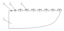
Fig. 1 is the structural representation of the utility model roll squeezer roll surface embodiment 1;
Fig. 2 is the side structure sketch map of Fig. 1.
Among the figure, 1-roll surface, 2-huge pillar nail, pillar nail of 3-, No. two pillar nails of 4-.
The specific embodiment
Below in conjunction with specific embodiment and accompanying drawing the utility model is further described.
Disclosed all characteristics in this specification, or the step in disclosed all methods or the process are except the speciality of mutual repulsion and/or the step; All can make up by any way; Only if special narration all can be replaced by other equivalences or the alternative features with similar purpose, promptly; Only if special narration, an embodiment in a series of equivalences of each characteristic or the similar characteristics.
The utility model roll squeezer roll surface comprises that dislocation is uniformly clouded in the 3 and No. two pillar nails 4 of 2, pillar nails of huge pillar nail on the roll surface 1; Said pillar nail 3 is located on the room between the roll surface 1 edge two huge pillars nail 2; No. two pillars nail 4 is located at the outward flange of roll surface 1, and No. two pillar nails 4 are a gather circle or more than the circle of dislocation evenly.Said roll surface is processed by high strength steel, and said huge pillar nail, a pillar nail and No. two pillar nails are processed by carbide alloy.
The height of appearing of said No. two pillars nail is followed closely less than huge pillar; Appearing of said pillar nail highly is less than or equal to the height of appearing of huge pillar nail.The diameter of said huge pillar nail is φ 10~φ 30mm, and it is appeared highly is 0~20mm; The diameter of said pillar nail is φ 3~φ 20mm, and it is appeared highly is 0~20mm; The diameter of said No. two pillars nail is φ 3~φ 20mm, and it is appeared is 0~15mm.
Like Fig. 1, shown in Figure 2; The diameter of said huge pillar nail 2 is φ 22mm, appears highly to be 10mm, and the diameter of a pillar nail 3 is φ 12mm; Appear and highly be 8mm; The diameter of No. two pillar nails 4 is φ 12mm, appears highly to be 4mm, and No. two pillar nails 4 are that the even dislocation of two circles is gathered in the roll surface outermost edge.
Embodiment 2
The diameter of huge pillar nail is φ 15mm, appears highly to be 8mm, and the diameter of a pillar nail is φ 8mm, and appearing highly is 5mm, and the diameter of No. two pillar nails is φ 8mm, appears highly to be 2mm.
Huge pillar nail, a pillar nail and No. two pillar nails all adopt the wearable hard alloy material manufacturing to form, and not only there is this wearable hard alloy post nail at the roll surface middle part, and also there is this wearable hard alloy post nail at the roll surface edge, makes on the whole roll surface and can both obtain wear-resistant protection; Adopt the pillar nail can make its layout closeer; The manufacturing cost of pillar nail is lower, and therefore not only the roller matrix more can be effectively protected, and makes the life-span at roll surface edge the same with the life-span at roll surface middle part; Improved the service life of whole roll surface; And reduced the manufacturing cost of roll surface, reduce the maintenance at pair of rollers edge, and then effectively improved operation rate.
The above is merely the preferred embodiment of the utility model; Not in order to restriction the utility model; Any modification of being done within all spirit and principles at the utility model, be equal to replacement and improvement etc., all should be included within the protection domain of the utility model.
Claims (6)
1. roll squeezer roll surface; Comprise that dislocation is uniformly clouded in the huge pillar nail (2) on the roll surface (1); It is characterized in that: also comprise a pillar nail (3) and No. two pillar nails (4); Said pillar nail (3) is located on the room between roll surface (1) the edge two huge pillars nails (2), and No. two pillar nails (4) are located at the outward flange of roll surface (1).
2. roll squeezer roll surface as claimed in claim 1 is characterized in that: said No. two pillars nails (4) are a gather circle or more than the circle of dislocation evenly.
3. roll squeezer roll surface as claimed in claim 2 is characterized in that: the height of appearing of said No. two pillars nails (4) is less than huge pillar nail (2); Appearing of said pillar nail (4) highly is less than or equal to the height of appearing of huge pillar nail (2).
4. roll squeezer roll surface as claimed in claim 3 is characterized in that: the diameter of said huge pillar nail (2) is φ 10~φ 30mm, and it is appeared highly is 0~20mm.
5. roll squeezer roll surface as claimed in claim 3 is characterized in that: the diameter of said pillar nail (3) is φ 3~φ 20mm, and it is appeared highly is 0~20mm.
6. roll squeezer roll surface as claimed in claim 3 is characterized in that: the diameter of said No. two pillars nails (4) is φ 3~φ 20mm, and it is appeared is 0~15mm.
Priority Applications (1)
| Application Number | Priority Date | Filing Date | Title |
|---|---|---|---|
| CN2012200890584U CN202497901U (en) | 2012-03-12 | 2012-03-12 | Roll surface of rolling machine |
Applications Claiming Priority (1)
| Application Number | Priority Date | Filing Date | Title |
|---|---|---|---|
| CN2012200890584U CN202497901U (en) | 2012-03-12 | 2012-03-12 | Roll surface of rolling machine |
Publications (1)
| Publication Number | Publication Date |
|---|---|
| CN202497901U true CN202497901U (en) | 2012-10-24 |
Family
ID=47034529
Family Applications (1)
| Application Number | Title | Priority Date | Filing Date |
|---|---|---|---|
| CN2012200890584U Expired - Lifetime CN202497901U (en) | 2012-03-12 | 2012-03-12 | Roll surface of rolling machine |
Country Status (1)
| Country | Link |
|---|---|
| CN (1) | CN202497901U (en) |
Cited By (1)
| Publication number | Priority date | Publication date | Assignee | Title |
|---|---|---|---|---|
| CN102600925A (en) * | 2012-03-12 | 2012-07-25 | 成都利君实业股份有限公司 | Roll face of roller press |
-
2012
- 2012-03-12 CN CN2012200890584U patent/CN202497901U/en not_active Expired - Lifetime
Cited By (2)
| Publication number | Priority date | Publication date | Assignee | Title |
|---|---|---|---|---|
| CN102600925A (en) * | 2012-03-12 | 2012-07-25 | 成都利君实业股份有限公司 | Roll face of roller press |
| CN102600925B (en) * | 2012-03-12 | 2014-07-30 | 成都利君实业股份有限公司 | Roll face of roller press |
Similar Documents
| Publication | Publication Date | Title |
|---|---|---|
| CN211677983U (en) | Hard alloy stud roll surface for rolling machine | |
| CN104307592A (en) | Roller side face anti-wearing device for roller press and high-pressure roller mill | |
| CN202666913U (en) | Lateral baffle for roll sleeve of roller mill | |
| CN102350391B (en) | Hard alloy stud roller surface | |
| CN102600925B (en) | Roll face of roller press | |
| CN101823011A (en) | Stud type roll surface structure for rolling mill and method for replacing stud | |
| CN202845081U (en) | High wear resistance composite rolling mortar wall/crushing wall of cone crusher | |
| CN202497901U (en) | Roll surface of rolling machine | |
| CN102397802B (en) | A kind of Novel squeeze roller type roller surface structure | |
| CN204672324U (en) | A kind of roll squeezer of exempting from build-up wear-resistant compression roller and using this compression roller | |
| CN102896013A (en) | Roller mill and self-synchronizing wearing roller of high-pressure roller mill | |
| CN204571988U (en) | A kind of cutter head | |
| CN104028945B (en) | A kind of Roller of High post tooth broken teeth method for repairing and mending | |
| CN203196677U (en) | Novel roll sleeve end surface protector of high-pressure roller mill | |
| CN201894946U (en) | Pressure double roll machine | |
| CN203470077U (en) | High-wear-resistant impacting and breaking knife head with hammer handle brazed by hard alloy | |
| CN202538837U (en) | Roller with protective edge | |
| CN102626663A (en) | Roller with safe edge | |
| CN104549654A (en) | Abrasion-resistant device between grinding roller sleeve and grinding table lining plate for vertical grinder | |
| CN216826471U (en) | Anti-jamming hammer crusher with low powder rate | |
| CN201969585U (en) | Roller with corner protection device | |
| CN204662226U (en) | Heavy reducing mechanism | |
| CN105879961B (en) | A kind of high-pressure roller mill of controllable particle size for chemical field | |
| CN204234136U (en) | A kind of high-pressure roller mill with roller skin protective layer | |
| CN213528865U (en) | Roll squeezer protection roller shell and breaker |
Legal Events
| Date | Code | Title | Description |
|---|---|---|---|
| C14 | Grant of patent or utility model | ||
| GR01 | Patent grant | ||
| CX01 | Expiry of patent term |
Granted publication date: 20121024 |
|
| CX01 | Expiry of patent term |