CN202497875U - Reactor - Google Patents
Reactor Download PDFInfo
- Publication number
- CN202497875U CN202497875U CN2012200308521U CN201220030852U CN202497875U CN 202497875 U CN202497875 U CN 202497875U CN 2012200308521 U CN2012200308521 U CN 2012200308521U CN 201220030852 U CN201220030852 U CN 201220030852U CN 202497875 U CN202497875 U CN 202497875U
- Authority
- CN
- China
- Prior art keywords
- stirring
- shaft
- reactor
- stirring vane
- kettle
- Prior art date
- Legal status (The legal status is an assumption and is not a legal conclusion. Google has not performed a legal analysis and makes no representation as to the accuracy of the status listed.)
- Expired - Fee Related
Links
- 238000003756 stirring Methods 0.000 claims abstract description 35
- 238000007599 discharging Methods 0.000 claims description 7
- 238000006243 chemical reaction Methods 0.000 abstract description 11
- 239000006260 foam Substances 0.000 abstract description 9
- 238000004140 cleaning Methods 0.000 abstract description 4
- 239000000376 reactant Substances 0.000 abstract description 2
- OKKJLVBELUTLKV-UHFFFAOYSA-N Methanol Chemical compound OC OKKJLVBELUTLKV-UHFFFAOYSA-N 0.000 description 3
- 239000000126 substance Substances 0.000 description 3
- QAOWNCQODCNURD-UHFFFAOYSA-N Sulfuric acid Chemical compound OS(O)(=O)=O QAOWNCQODCNURD-UHFFFAOYSA-N 0.000 description 2
- 238000005516 engineering process Methods 0.000 description 2
- 230000032050 esterification Effects 0.000 description 2
- 238000005886 esterification reaction Methods 0.000 description 2
- HLLSOEKIMZEGFV-UHFFFAOYSA-N 4-(dibutylsulfamoyl)benzoic acid Chemical compound CCCCN(CCCC)S(=O)(=O)C1=CC=C(C(O)=O)C=C1 HLLSOEKIMZEGFV-UHFFFAOYSA-N 0.000 description 1
- 230000009286 beneficial effect Effects 0.000 description 1
- 230000007812 deficiency Effects 0.000 description 1
- 230000000694 effects Effects 0.000 description 1
- 239000000463 material Substances 0.000 description 1
- 230000004048 modification Effects 0.000 description 1
- 238000012986 modification Methods 0.000 description 1
- 238000007634 remodeling Methods 0.000 description 1
- 230000009466 transformation Effects 0.000 description 1
Images
Landscapes
- Physical Or Chemical Processes And Apparatus (AREA)
Abstract
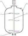
A reactor comprises a reactor body, stirring blades, a stirring shaft, a feed inlet and a discharge outlet. The stirring shaft is mounted inside the reactor body, the stirring blades are fixed on the stirring shaft, the feed inlet is arranged at the top of the reactor body, and the discharge outlet is arranged at the bottom of the reactor body. The reactor is characterized in that the three sets of stirring blades are mounted at the upper end, in the middle and at the lower end of the stirring shaft respectively. The stirring blades are mounted at the upper end, in the middle, and at the lower end of the stirring shaft respectively, the stirring blade at the lower end is used for stirring reactant, the stirring blades in the middle and at the upper end can break and eliminate foams produced in reaction, and accordingly reaction efficiency is improved, work load of cleaning the reactor is reduced, and cost and manpower are economized.
Description
Technical field
The utility model belongs to the chemical industry equipment field, is specifically related to a kind of agitated reactor, is the transformation to the agitated reactor structure in the prior art.
Background technology
At present, a lot of chemical plant and pharmaceutical factory all be unable to do without agitated reactor.Agitated reactor of the prior art generally includes kettle and shaft, is provided with one group of stirring vane on the shaft usually, and stirring vane is arranged on the bottom of shaft.When shaft rotated, stirring vane only can stir still internal reaction thing.And for some reaction, like esterification, when temperature is elevated to 68 ℃; Stir through blade; Can produce significant foam in the agitated reactor, stirring vane of the prior art can't be handled the foam in the agitated reactor, and the existence of significant foam has had a strong impact on reaction effect and cleaning afterwards.
Summary of the invention
The technical problem that the utility model will solve is: overcome the deficiency of prior art, a kind of agitated reactor is provided, can eliminate the bubble that substance reaction is produced in the agitated reactor, improve reaction efficiency.
The utility model solves the technical scheme that its technical problem adopted: design a kind of agitated reactor, comprise kettle, stirring vane, shaft, charging aperture and discharging opening; Shaft is installed in kettle inside; Stirring vane is fixed on the shaft, and charging aperture is arranged on the kettle top, and discharging opening is arranged on autoclave body bottom; Stirring vane is three groups, is installed in upper end, middle part and the lower end of shaft respectively.
Compared with prior art, the beneficial effect of the utility model is:
Upper end, middle part and lower end through at shaft are installed stirring vane respectively, and the stirring vane of bottom is used for stirring reaction
Thing, the stirring vane on middle part and top can be smashed the foam that reaction is produced, and eliminates foam, has improved reaction efficiency; Reduced the workload of agitated reactor cleaning, provided cost savings and manpower.
Description of drawings
Fig. 1 is the utility model structural representation.
Be labeled as among the figure:
1, kettle; 3, stirring vane; 2, shaft; 4, charging aperture; 5, discharging opening.
The specific embodiment
Below in conjunction with accompanying drawing and embodiment, the utility model done further describing:
As shown in Figure 1, a kind of agitated reactor comprises kettle 1, stirring vane 3, shaft 2; Charging aperture 4 and discharging opening 5, shaft 2 is installed in kettle 1 inside, and stirring vane 3 is fixed on the shaft 2; Charging aperture 4 is arranged on kettle 1 top; Discharging opening 5 is arranged on kettle 1 bottom, and stirring vane 3 is three groups, is installed in upper end, middle part and the lower end of shaft 2 respectively.
The utility model operation principle and the course of work are following:
Methyl alcohol, sulfuric acid and the Gu Long acid of in kettle 1, injecting certain proportioning through charging aperture 4, the reactant of the 3 pairs of kettlies 1 of stirring vane through being positioned at shaft 2 lower ends stirs.Heat in the kettle 1, when temperature was elevated to 68 ℃, esterification produced significant foam.At this moment, the stirring vane 3 that is arranged on shaft 2 middle parts and upper end is smashed foam, and foam constantly produces and constantly is stirred blade 3 and eliminates, and has improved reaction efficiency greatly, has reduced the workload of agitated reactor cleaning, has saved the man power and material.
The above; It only is the preferred embodiment of the utility model; Be not to be the restriction of the utility model being made other form, any professional and technical personnel of being familiar with possibly utilize the technology contents of above-mentioned announcement to change or be modified as the equivalent embodiment of equivalent variations.But every the utility model technical scheme content that do not break away to any simple modification, equivalent variations and remodeling that above embodiment did, still belongs to the protection domain of the utility model technical scheme according to the technical spirit of the utility model.
Claims (1)
1. an agitated reactor comprises kettle (1), stirring vane (3), shaft (2), charging aperture (4) and discharging opening (5); Said shaft (2) is installed in kettle (1) inside; Said stirring vane (3) is fixed on the shaft (2), and charging aperture (4) is arranged on kettle (1) top, and discharging opening (5) is arranged on kettle (1) bottom; It is characterized in that: said stirring vane (3) is three groups, is installed in upper end, middle part and the lower end of shaft (2) respectively.
Priority Applications (1)
| Application Number | Priority Date | Filing Date | Title |
|---|---|---|---|
| CN2012200308521U CN202497875U (en) | 2012-01-31 | 2012-01-31 | Reactor |
Applications Claiming Priority (1)
| Application Number | Priority Date | Filing Date | Title |
|---|---|---|---|
| CN2012200308521U CN202497875U (en) | 2012-01-31 | 2012-01-31 | Reactor |
Publications (1)
| Publication Number | Publication Date |
|---|---|
| CN202497875U true CN202497875U (en) | 2012-10-24 |
Family
ID=47034503
Family Applications (1)
| Application Number | Title | Priority Date | Filing Date |
|---|---|---|---|
| CN2012200308521U Expired - Fee Related CN202497875U (en) | 2012-01-31 | 2012-01-31 | Reactor |
Country Status (1)
| Country | Link |
|---|---|
| CN (1) | CN202497875U (en) |
-
2012
- 2012-01-31 CN CN2012200308521U patent/CN202497875U/en not_active Expired - Fee Related
Similar Documents
| Publication | Publication Date | Title |
|---|---|---|
| CN202447086U (en) | Stainless steel reaction kettle | |
| CN202778360U (en) | High-shear emulsification tank | |
| CN202497875U (en) | Reactor | |
| CN203291860U (en) | Stirring reaction kettle | |
| CN203002271U (en) | Dislocated blade stirrer | |
| CN204710200U (en) | A kind of comminuting dasher | |
| CN201894917U (en) | Fluid mixer | |
| CN205223157U (en) | High -efficient convenient preparation of bio -diesel device | |
| CN203663832U (en) | Chemical reaction kettle | |
| CN203295208U (en) | White carbon black filter cake pulping tank | |
| CN202983576U (en) | White carbon black stirring pot | |
| CN202921304U (en) | Environment-friendly sulfur dyestuff reaction kettle | |
| CN203469829U (en) | Improved efficient pipeline mixer | |
| CN202010556U (en) | Reaction kettle | |
| CN205170767U (en) | Utilize waste oil preparation biodiesel system | |
| CN205223116U (en) | Reaction device for manufacturing biodiesel | |
| CN203577786U (en) | Novel reaction kettle | |
| CN203874772U (en) | Reaction kettle for mixing | |
| CN202161992U (en) | Efficient hydrogenation kettle | |
| CN203710949U (en) | Coal slurry mixing stirrer | |
| CN204672186U (en) | High tower washing powder slip preparing tank structure | |
| CN203525701U (en) | Reaction tower kettle | |
| CN202399394U (en) | Propeller agitator | |
| CN203043976U (en) | Reactor | |
| CN205223156U (en) | High -efficient environmental protection biodiesel prepares device |
Legal Events
| Date | Code | Title | Description |
|---|---|---|---|
| C14 | Grant of patent or utility model | ||
| GR01 | Patent grant | ||
| C17 | Cessation of patent right | ||
| CF01 | Termination of patent right due to non-payment of annual fee |
Granted publication date: 20121024 Termination date: 20140131 |