CN202497839U - Improved heat conduction material stirring device - Google Patents
Improved heat conduction material stirring device Download PDFInfo
- Publication number
- CN202497839U CN202497839U CN2012201671014U CN201220167101U CN202497839U CN 202497839 U CN202497839 U CN 202497839U CN 2012201671014 U CN2012201671014 U CN 2012201671014U CN 201220167101 U CN201220167101 U CN 201220167101U CN 202497839 U CN202497839 U CN 202497839U
- Authority
- CN
- China
- Prior art keywords
- linear bearing
- paddle
- heat conduction
- head
- conduction material
- Prior art date
- Legal status (The legal status is an assumption and is not a legal conclusion. Google has not performed a legal analysis and makes no representation as to the accuracy of the status listed.)
- Expired - Lifetime
Links
- 239000000463 material Substances 0.000 title claims abstract description 14
- 238000003756 stirring Methods 0.000 title abstract description 17
- 230000007774 longterm Effects 0.000 abstract description 4
- 230000009286 beneficial effect Effects 0.000 abstract description 2
- 230000000694 effects Effects 0.000 description 2
- 210000003141 lower extremity Anatomy 0.000 description 2
- 238000007790 scraping Methods 0.000 description 2
- 230000008878 coupling Effects 0.000 description 1
- 238000010168 coupling process Methods 0.000 description 1
- 238000005859 coupling reaction Methods 0.000 description 1
- 238000005516 engineering process Methods 0.000 description 1
- 239000000945 filler Substances 0.000 description 1
- 230000005484 gravity Effects 0.000 description 1
- 239000007788 liquid Substances 0.000 description 1
- 238000000034 method Methods 0.000 description 1
- 239000011347 resin Substances 0.000 description 1
- 229920005989 resin Polymers 0.000 description 1
- 230000000630 rising effect Effects 0.000 description 1
- 238000005096 rolling process Methods 0.000 description 1
Images
Landscapes
- Accessories For Mixers (AREA)
- Mixers Of The Rotary Stirring Type (AREA)
Abstract
The utility model relates to an improved heat conduction material stirring device. The improved heat conduction material stirring device comprises a machine head, a stirring paddle, a stirring tank and a machine body and is characterized in that the machine body comprises a bushing system, a shaft and a linear bearing; the shaft is connected with the inner ring of the linear bearing; the outer ring of the linear bearing is connected with the bushing system; the machine head is connected with the machine body; the stirring paddle is connected with the machine head and is arranged in the stirring tank; the stirring paddle and the center of the stirring tank are on the same straight line. The improved heat conduction material stirring device has the beneficial effects that as the high-accuracy linear bearing assembly is matched with the lining system, when the machine head ascends or descends, the friction between the shaft on the machine body and the linear bearing is lesser, the stirring paddle can be controlled to ascend or descend on a straight line for long term, and gaps exist between vanes of the stirring paddle and the stirring tank, and other positioning components are not needed to depend on.
Description
Technical field
The utility model relates to a kind of improved Heat Conduction Material agitating device.
Background technology
Heat Conduction Material is mixed by various resin liquid and high heat filling and forms, and the filler addition is all very high, and viscosity is relatively large; Difficult mixing; This requires very high to mixer, if stir inhomogeneously, can directly have influence on the thermal conductivity and the mechanical property of Heat Conduction Material.The fuselage of tradition mixer adopts the connecting rod of low accuracy and the up-down that liner system is controlled mixer head and shaft, and after long-term the use, the contact area of connecting rod and shaft is big; Friction level is big, often can not let shaft rise accurately more point-blank and descend, and paddle departs from the center of agitator tank; Occur contact between one side of stirrer paddle and the agitator tank, very big gap is arranged between the another side of blade and the agitator tank, scraping appears in stirrer paddle and agitator tank inwall sometimes during stirring; Mix inhomogeneous; When letting head rise when needs lifting paddle, owing to departing from of center, head is not just can rise very smoothly.In order to let paddle be in the agitator tank center, take normal adjusting agitator tank position, or be provided with other position limiting structure at the mixer head, as shown in Figure 1.
Summary of the invention
The purpose of the utility model; Be that a kind of improved Heat Conduction Material agitating device will be provided; It has done improvement to fuselage, adopts high-precision linear bearing assembly to substitute low connecting rod for low precision, lets paddle in the agitator tank center; Gapped between stirrer paddle and the agitator tank, need not to rely on other position limiting structures.
The utility model is to realize like this; Said a kind of improved Heat Conduction Material agitating device; It comprises head, paddle, agitator tank, fuselage; It is characterized in that: said fuselage is made up of liner system, axle, linear bearing, and axle is connected with the linear bearing inner ring, and the linear bearing outer ring is connected with liner system; Head is connected with fuselage, and paddle is connected with head, paddle in agitator tank, and with the agitator tank center point-blank.
The beneficial effect of the utility model is; Adopt high-precision linear bearing assembly to cooperate liner system; Head rise and fall axle on one's body on opportunity is less with the friction of linear bearing; But the rise and fall point-blank of long-term control paddle let between stirrer paddle and the agitator tank gappedly, and need not to rely on other spacing members.
Description of drawings
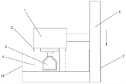
Fig. 1 is traditional Heat Conduction Material mixer sketch map.
Fig. 2 is the utility model sketch map.
Among the figure: 1, head, 2, position limiting structure, 3, paddle, 4, the agitator tank after spacing, 5, agitator tank, 6, connecting rod, 7, liner system, 8, axle, 9, linear bearing, 10, the agitator tank after the skew.
The specific embodiment
When paddle dropped to the position in the agitator tank in the tradition mixer, as shown in Figure 1, fuselage was made up of connecting rod 6 and liner system 7; Paddle 3 is connected with head 1, and head 1 links to each other with connecting rod 6, under the effect of hydraulic coupling; Connecting rod 6 is slowly lifting of quilt in liner system 7; Head 1 is raised, and in the time will falling head 1, head 1 relies on gravity effect drivening rod 6 in liner system 7, to descend gradually.
After long-term rising and step-down operation, the sliding friction between connecting rod 6 and the liner system 7 increases, and the mutual alignment changes to some extent; For example connecting rod 6 has skew in the position in liner system 7, and in the whipping process, head 1 has swing with paddle 3; Agitator tank 10 after the skew needs the adjustment position; The center of the agitator tank 10 after the skew and paddle 3 not point-blank, one side of stirrer paddle with the skew after agitator tank in addition contact, cause the scraping of agitator tank; And the another side of stirrer paddle and agitator tank have big gap, and the Heat Conduction Material that stirs out like this is inhomogeneous.In order to address this problem, at head 1 lower limb, a position limiting structure 2 is set, make it with spacing after agitator tank 4 contact, the swing of restriction head 1, let paddle 3 with spacing after agitator tank 4 the center point-blank, guarantee evenly to stir.
The said a kind of improved Heat Conduction Material agitating device of the utility model; As shown in Figure 2; It comprises head 1, paddle 3, agitator tank 5, fuselage; Said fuselage by liner system 7, axle 8, linear bearing 9 forms, spools 8 are connected with linear bearing 9 inner rings, linear bearing 9 outer rings are connected with liner system 7; Head is connected with fuselage, and paddle 3 is connected with head 1, paddle 3 in agitator tank 5, and with the agitator tank center point-blank.When head rises or descend; The inner ball of linear bearing is rolling friction, and the connection contact friction between liner system, axle, the linear bearing is very little, can guarantee for a long time that the high precision of head rises, descend; Guarantee paddle and agitator tank center point-blank; All there is the gap that equates on the both sides of stirrer paddle with agitator tank, do not need at the head lower limb position limiting structure 2 to be set, and the rise and fall of head simultaneously can be obstructed.
Claims (1)
1. improved Heat Conduction Material agitating device; It comprises head, paddle, agitator tank, fuselage; It is characterized in that: said fuselage is made up of liner system, axle, linear bearing, and axle is connected with the linear bearing inner ring, and the linear bearing outer ring is connected with liner system; Head is connected with fuselage, and paddle is connected with head, paddle in agitator tank, and with the agitator tank center point-blank.
Priority Applications (1)
| Application Number | Priority Date | Filing Date | Title |
|---|---|---|---|
| CN2012201671014U CN202497839U (en) | 2012-04-19 | 2012-04-19 | Improved heat conduction material stirring device |
Applications Claiming Priority (1)
| Application Number | Priority Date | Filing Date | Title |
|---|---|---|---|
| CN2012201671014U CN202497839U (en) | 2012-04-19 | 2012-04-19 | Improved heat conduction material stirring device |
Publications (1)
| Publication Number | Publication Date |
|---|---|
| CN202497839U true CN202497839U (en) | 2012-10-24 |
Family
ID=47034467
Family Applications (1)
| Application Number | Title | Priority Date | Filing Date |
|---|---|---|---|
| CN2012201671014U Expired - Lifetime CN202497839U (en) | 2012-04-19 | 2012-04-19 | Improved heat conduction material stirring device |
Country Status (1)
| Country | Link |
|---|---|
| CN (1) | CN202497839U (en) |
-
2012
- 2012-04-19 CN CN2012201671014U patent/CN202497839U/en not_active Expired - Lifetime
Similar Documents
| Publication | Publication Date | Title |
|---|---|---|
| CN203782216U (en) | Feeding mechanism and mixing device for preparing hard alloy from powder metallurgy | |
| CN204261590U (en) | A kind of liquid material agitating device | |
| CN204261671U (en) | A kind of stirred autoclave | |
| CN204524321U (en) | A kind of perforating device | |
| CN203777980U (en) | Feeding device of powder stirring machine | |
| CN202497839U (en) | Improved heat conduction material stirring device | |
| CN105152113A (en) | Filling machine | |
| CN202105462U (en) | Stirring paddle | |
| CN203591738U (en) | Emulsion paint stirring machine | |
| CN206837923U (en) | A kind of travelling mixer | |
| CN203862198U (en) | Novel stirring rod for powder mixed materials | |
| CN204193838U (en) | A kind of mixing plant | |
| CN203886492U (en) | Novel stirring structure | |
| CN104056562B (en) | Automatic multi-liquid mixing device | |
| CN206258342U (en) | Rotation viscometer | |
| CN205517453U (en) | Fixed telescopic agitator | |
| CN204502849U (en) | The mixer that a kind of stirrer paddle is swingable | |
| CN203990504U (en) | A kind of paddle and agitating device | |
| CN203494463U (en) | Stirring shaft | |
| CN203874724U (en) | Helical ribbon paddle | |
| CN201524444U (en) | Extracting and stirring device for Chinese medicine | |
| CN205196965U (en) | Food preparation machine combination stirring blade | |
| CN207755807U (en) | A kind of agitating device in Chinese medicine extracting tank | |
| CN204182352U (en) | A kind of Double-layer stirring paddle | |
| CN206519076U (en) | A kind of mixing unit produced for conduit pellet |
Legal Events
| Date | Code | Title | Description |
|---|---|---|---|
| C14 | Grant of patent or utility model | ||
| GR01 | Patent grant | ||
| CX01 | Expiry of patent term |
Granted publication date: 20121024 |
|
| CX01 | Expiry of patent term |