CN202497720U - Toy aircraft - Google Patents
Toy aircraft Download PDFInfo
- Publication number
- CN202497720U CN202497720U CN201220084764XU CN201220084764U CN202497720U CN 202497720 U CN202497720 U CN 202497720U CN 201220084764X U CN201220084764X U CN 201220084764XU CN 201220084764 U CN201220084764 U CN 201220084764U CN 202497720 U CN202497720 U CN 202497720U
- Authority
- CN
- China
- Prior art keywords
- fixed
- center
- toy aircraft
- gravity
- rotatable frame
- Prior art date
- Legal status (The legal status is an assumption and is not a legal conclusion. Google has not performed a legal analysis and makes no representation as to the accuracy of the status listed.)
- Expired - Fee Related
Links
- 230000005484 gravity Effects 0.000 claims abstract description 60
- 230000037431 insertion Effects 0.000 claims description 3
- 238000003780 insertion Methods 0.000 claims description 3
- 230000000694 effects Effects 0.000 abstract 1
- 238000004519 manufacturing process Methods 0.000 description 3
- 239000002537 cosmetic Substances 0.000 description 2
- 238000005516 engineering process Methods 0.000 description 2
- 239000000463 material Substances 0.000 description 2
- 230000009286 beneficial effect Effects 0.000 description 1
Images


Landscapes
- Toys (AREA)
Abstract
Provided is a toy aircraft which comprises a fixation rack, a rotatable rack and a propeller actuating mechanism, wherein the propeller actuating mechanism is fixed on the rotatable rack, and the rotatable rack is rotatably fixed on the fixation rack. The toy aircraft is characterized in that the toy craft further comprises at least one gravity adjusting mechanism which can adjust the gravity of the toy aircraft, wherein the gravity adjusting mechanism is disposed between the fixation rack and the rotatable rack. Compared with the prior art, the toy aircraft has the following effects that since the gravity adjusting mechanism can change the gravity of the toy aircraft, the toy aircraft can deflect, and the direction of the propeller which is fixed on the rotatable rack can be changed, and thus the flying direction of the toy aircraft can be changed; the toy aircraft is simple in structure, small in volume, and flexible and fast in direction change; furthermore, the toy aircraft has variable appearances, and thus the amusement and playability of the toy aircraft are substantially improved.
Description
Technical field
The utility model relates to a kind of flying toy, more specifically to a kind of toy aircraft that can flexibly change of flight direction.
Background technology
Existing flying toy all is toy airplane usually, and in order to let toy airplane can possess the function that turns to, two kinds of schemes is arranged usually.
A kind of scheme is provided with aileron rudder face, screw-rudder etc. at the toy airplane afterbody, waits through aileron rudder face, screw-rudder to change direction.
Another kind of scheme then is in the left and right sides of toy airplane a screw actuating unit to be set respectively, and the difference through two screw actuating unit revolution speed of propeller changes direction.
Though but above-mentioned two kinds of schemes can both let toy airplane possess turning efficiency; But all there are complex structure, manufacturing cost height, turn to shortcomings such as dumb; And adopt the profile of aircraft to make that the profile of above-mentioned these toys is similar, and its height is obviously longer with respect to height and width.This structure makes toy airplane change difficulty of direction ratio.
Summary of the invention
The utility model technical problem to be solved be high to the toy airplane complex structure of prior art, manufacturing cost, turn to shortcomings such as dumb; A kind of toy aircraft is provided, this toy aircraft is simple in structure, low cost of manufacture, turn to very flexible.The technical scheme that adopts is following:
A kind of toy aircraft; Comprise fixed mount, rotatable frame and screw actuating unit; Said screw actuating unit is fixed on the rotatable frame; Said rotatable frame is rotating to be fixed on the fixed mount, it is characterized in that: said toy aircraft also comprises the center of gravity governor motion of at least one scalable toy aircraft center of gravity, and said center of gravity governor motion is located between fixed mount and the rotatable frame.
A kind of scheme, said center of gravity governor motion comprises motor, screw rod and nut, and said motor is fixed on the fixed mount, and screw rod is fixed on the motor output shaft, and nut sleeve is on screw rod, and nut connects rotatable frame.When the motor drives screw rod rotated, nut will drive rotatable frame relative fixed frame and rotate along screw motion, thereby changes scalable toy aircraft center of gravity.Nut preferably adopts connecting ring, linkage etc. to connect rotatable frame.Also can motor be set on the rotatable frame, let the nut Connection Bracket.
Another kind of scheme, said turning set up rotating shaft, and said center of gravity governor motion comprises motor, gear drive and center of gravity adjusting gear; Motor and gear drive are fixed on the rotatable frame; The center of gravity adjusting gear is rotating to be fixed in the rotating shaft that turns frame, and the input gear of gear drive is fixed on the output shaft of motor, the output gear of gear drive and the engagement of center of gravity adjusting gear; The lateral surface of said center of gravity adjusting gear departs from rotating shaft place and is provided with sliding bar; Said fixed mount bottom is provided with two limited posts, forms chute between two limited posts, and said sliding bar can be in the insertion chute of chute slip.
More excellent scheme, said center of gravity adjusting gear is fan-shaped.Can save the material and the occupation space of center of gravity adjusting gear so as much as possible.
For the ease of the reposition of center of gravity adjusting gear; Said center of gravity governor motion also comprises the return torsion spring; The medial surface of said center of gravity adjusting gear is provided with locating piece, and said return torsion spring is fixed in the rotating shaft, and the top of two elastic recoil bars of return torsion spring lays respectively at the both sides of locating piece.After the center of gravity adjusting gear rotated an angle, elastic recoil bar of locating piece compressing made this elastic recoil warpage of rod.When motor quits work, this elastic recoil bar just drives the center of gravity adjusting gear and gets back to original position.
More excellent scheme, said screw actuating unit comprises driving mechanism and screw, and said driving mechanism is located at rotatable frame bottom, and said screw is rotating to be fixed on the rotatable frame, and said driving mechanism connects screw.
More excellent scheme, said toy aircraft also comprises housing, and said housing is fixed on the fixed mount, and case cover is in rotatable frame and the fixed mount outside, and case top has the through hole that can let the fixed axis of screw pass.Housing can effectively be protected parts in the housing, and can also beautify the outward appearance of toy aircraft.
More excellent scheme, said toy aircraft also comprises underframe and control device, and said underframe is fixed on the housing bottom, and said control device is fixed on the underframe.Said control device comprises control circuit, power supply etc., because the control device of this control device and common remote-control toy aircraft is basic identical, can adopt the control device of common remote-control toy aircraft fully, does not therefore add to describe.
The utility model beneficial effect against existing technologies is; Because the center of gravity governor motion can change the center of gravity of toy aircraft, so toy aircraft can deflect, and the direction that is fixed on the screw on the rotatable frame can change; Thereby let the direction of toy aircraft flight change; It is simple in structure, volume is less, break-in is quick flexibly, and its cosmetic variation multiterminal, and interesting, playability significantly improves.
Description of drawings
Fig. 1 is the structural representation of the utility model embodiment 1;
Fig. 2 is the exploded view of embodiment 1;
Fig. 3 is the structural representation of fixed mount among the embodiment 1, rotatable frame, center of gravity governor motion;
Fig. 4 is the structural representation of rotatable frame, center of gravity governor motion among the embodiment 1;
Fig. 5 is that the center of gravity governor motion unloads the structural representation behind the center of gravity adjusting gear among the embodiment 1;
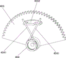
Fig. 6 is the center of gravity adjusting gear of center of gravity governor motion among the embodiment 1 and the structural representation of return torsion spring;
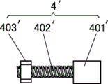
Fig. 7 is the structural representation of the center of gravity governor motion of embodiment 2.
The specific embodiment
Embodiment 1
Shown in Fig. 1-6, the toy aircraft in the present embodiment comprises fixed mount 1, rotatable frame 2 and screw actuating unit, and said screw actuating unit 3 is fixed on the rotatable frame 2, said rotatable frame 2 rotating being fixed on the fixed mount 1.Said toy aircraft also comprises the center of gravity governor motion 4 of a scalable toy aircraft center of gravity, and said center of gravity governor motion 4 is located between fixed mount 1 and the rotatable frame 2.
Said rotatable frame 2 is provided with rotating shaft 201; Said center of gravity governor motion 4 comprises motor 401, gear drive 402 and center of gravity adjusting gear 403; Motor 401 is fixed on the rotatable frame 2 with gear drive 402; Center of gravity adjusting gear 403 rotating being fixed in the rotating shaft 201 that turns frame 2, the input gear of gear drive 402 is fixed on the output shaft of motor 401, the output gear of gear drive 402 and 403 engagements of center of gravity adjusting gear; The lateral surface of said center of gravity adjusting gear 403 departs from rotating shaft 201 places and is provided with sliding bar 4031; Said fixed mount 1 bottom is provided with and forms chute 102 between 101, two limited posts 101 of two limited posts, and said sliding bar 4031 can be in the insertion chute 102 of chute 102 slips.
Said center of gravity adjusting gear 403 is fan-shaped.Can save the material and the occupation space of center of gravity adjusting gear 403 so as much as possible.
For the ease of 403 repositions of center of gravity adjusting gear; Said center of gravity governor motion 4 also comprises return torsion spring 404; The medial surface of said center of gravity adjusting gear 403 is provided with locating piece 4032; Said return torsion spring 404 is fixed in the rotating shaft 201, and the top of two elastic recoil bars 4041 of return torsion spring 404 lays respectively at the both sides of locating piece 4032.After center of gravity adjusting gear 403 rotated an angle, elastic recoil bar 4041 of locating piece 4032 compressings made this elastic recoil bar 4041 twist.When motor 401 quits work, this elastic recoil bar 4041 just drives center of gravity adjusting gear 403 and gets back to original position.
Said screw actuating unit 3 comprises screw 301 and driving mechanism 302, and said driving mechanism 302 is located at rotatable frame 2 bottoms, said screw 301 rotating being fixed on the rotatable frame 2, and said driving mechanism 302 connects screw 301.
Said toy aircraft also comprises housing 5, and said housing 5 is fixed on the fixed mount 1, and housing 5 covers on the rotatable frame 2 and fixed mount 1 outside, and housing 5 tops have the through hole 501 that can let the fixed axis of screw 301 pass.Said housing 5 can effectively be protected parts in the housing 5, and can also beautify the outward appearance of toy aircraft.
Said toy aircraft also comprises underframe 6 and control device 7, and said underframe 6 is fixed on housing 5 bottoms, and said control device 7 is fixed on the underframe 6.Said control device 7 comprises control circuit, power supply etc., because this control device 7 is basic identical with the control device 7 of common remote-control toy aircraft, can adopt the control device 7 of common remote-control toy aircraft fully, does not therefore add to describe.
The edge of said underframe 6 also is provided with a plurality of cosmetic sheet 8, can let toy aircraft more good-looking like this.
As shown in Figure 7, the difference of toy aircraft in the present embodiment and embodiment 1 is:
Said center of gravity governor motion 4 ' comprise motor 401 ', screw rod 402 ' and nut 403 '; Said motor 401 ' be fixed on the fixed mount 1; Screw rod 402 ' be fixed on motor 401 ' output shaft, nut 403 ' be enclosed within screw rod 402 ' on, and the rotatable frame 2 of nut 403 ' connection.In the time of motor 401 ' drive screw rod 402 ' rotation, nut 403 ' will drive rotatable frame 2 relative fixed framves 1 and rotate, thereby change scalable toy aircraft center of gravity along screw rod 402 ' move.Nut 403 ' employing connecting ring connects rotatable frame 2.Also can be with on the rotatable frame 2 of motor 401 ' be set to, let nut 403 ' Connection Bracket 1.
The above is merely two preferred embodiments of the utility model, is not the practical range that is used for limiting the utility model; Be all equivalents of being done according to the claim scope of the utility model, be the utility model claim scope and cover.
Claims (8)
1. toy aircraft; Comprise fixed mount, rotatable frame and screw actuating unit; Said screw actuating unit is fixed on the rotatable frame; Said rotatable frame is rotating to be fixed on the fixed mount, it is characterized in that: said toy aircraft also comprises the center of gravity governor motion of at least one scalable toy aircraft center of gravity, and said center of gravity governor motion is located between fixed mount and the rotatable frame.
2. toy aircraft as claimed in claim 1; It is characterized in that: said center of gravity governor motion comprises motor, screw rod and nut, and said motor is fixed on the fixed mount, and screw rod is fixed on the motor output shaft; Nut sleeve is on screw rod, and nut connects rotatable frame.
3. toy aircraft as claimed in claim 1; It is characterized in that: the said rotatable rotating shaft of having set up; Said center of gravity governor motion comprises motor, gear drive and center of gravity adjusting gear, and motor and gear drive are fixed on the rotatable frame, and the center of gravity adjusting gear is rotating to be fixed in the rotating shaft that turns frame; The input gear of gear drive is fixed on the output shaft of motor; The output gear of gear drive and the engagement of center of gravity adjusting gear, the lateral surface of said center of gravity adjusting gear departs from rotating shaft place and is provided with sliding bar, and said fixed mount bottom is provided with two limited posts; Article two, form chute between the limited post, said sliding bar can be in the insertion chute of chute slip.
4. toy aircraft as claimed in claim 3 is characterized in that: said center of gravity adjusting gear is fan-shaped.
5. toy aircraft as claimed in claim 4; It is characterized in that: said center of gravity governor motion also comprises the return torsion spring; The medial surface of said center of gravity adjusting gear is provided with locating piece; Said return torsion spring is fixed in the rotating shaft, and the top of two elastic recoil bars of return torsion spring lays respectively at the both sides of locating piece.
6. like any described toy aircraft among the claim 1-5; It is characterized in that: said screw actuating unit comprises driving mechanism and screw; Said driving mechanism is located at rotatable frame bottom; Said screw is rotating to be fixed on the rotatable frame, and said driving mechanism connects screw.
7. like any described toy aircraft among the claim 1-5; It is characterized in that: said toy aircraft also comprises housing; Said housing is fixed on the fixed mount, and case cover is in rotatable frame and the fixed mount outside, and case top has the through hole that can let screw pass.
8. toy aircraft as claimed in claim 7 is characterized in that: said toy aircraft also comprises underframe and control device, and said underframe is fixed on the housing bottom, and said control device is fixed on the underframe.
Priority Applications (1)
| Application Number | Priority Date | Filing Date | Title |
|---|---|---|---|
| CN201220084764XU CN202497720U (en) | 2012-03-07 | 2012-03-07 | Toy aircraft |
Applications Claiming Priority (1)
| Application Number | Priority Date | Filing Date | Title |
|---|---|---|---|
| CN201220084764XU CN202497720U (en) | 2012-03-07 | 2012-03-07 | Toy aircraft |
Publications (1)
| Publication Number | Publication Date |
|---|---|
| CN202497720U true CN202497720U (en) | 2012-10-24 |
Family
ID=47034349
Family Applications (1)
| Application Number | Title | Priority Date | Filing Date |
|---|---|---|---|
| CN201220084764XU Expired - Fee Related CN202497720U (en) | 2012-03-07 | 2012-03-07 | Toy aircraft |
Country Status (1)
| Country | Link |
|---|---|
| CN (1) | CN202497720U (en) |
-
2012
- 2012-03-07 CN CN201220084764XU patent/CN202497720U/en not_active Expired - Fee Related
Similar Documents
| Publication | Publication Date | Title |
|---|---|---|
| CN203417464U (en) | Model airplane of single-airscrew multi-connecting-rod structure | |
| CN211611593U (en) | Multi-gear trigger triggering mechanism and game handle | |
| CN202358300U (en) | Variable pitch three-axis aircraft | |
| CN203780797U (en) | Double-motor variable-pitch multi-rotor aircraft | |
| CN202686727U (en) | Gesture adjusting mechanism of underwater gliding device | |
| CN203971397U (en) | Multi-functional deformation four-axle aircraft | |
| CN110588264A (en) | A ground-air amphibious drone | |
| CN202497720U (en) | Toy aircraft | |
| CN203303641U (en) | Toy car with gravity center adjusting function | |
| CN203921196U (en) | The folding sole flight's device of a kind of backpack box | |
| CN203264279U (en) | Multi-shaft flying machine | |
| CN204563606U (en) | Single shaft aircraft | |
| CN202569556U (en) | Toy helicopter | |
| CN219001968U (en) | Remote Control Glider Aircraft Model Control Mechanism and Its Remote Control Glider Aircraft Model | |
| CN205179212U (en) | Control panel business turn over storehouse mechanism | |
| CN216213070U (en) | Rotary limit switch | |
| CN201101893Y (en) | Telecontrolled model helicopter | |
| CN204485299U (en) | Planetary ferris wheel | |
| CN201101892Y (en) | Telecontrolled model helicopter | |
| CN205327404U (en) | Reaction torque aileron | |
| CN104971506B (en) | Composable whirligig | |
| CN202796592U (en) | Knob switch | |
| CN204601627U (en) | Upset flying wheel toy | |
| CN205850232U (en) | A kind of remote control modification toy car driving means | |
| CN204973061U (en) | Conveniently change motor aircraft |
Legal Events
| Date | Code | Title | Description |
|---|---|---|---|
| C14 | Grant of patent or utility model | ||
| GR01 | Patent grant | ||
| CF01 | Termination of patent right due to non-payment of annual fee |
Granted publication date: 20121024 Termination date: 20150307 |
|
| EXPY | Termination of patent right or utility model |