CN202497360U - Movable type central oxygen supply and aspiration medical ward bed - Google Patents
Movable type central oxygen supply and aspiration medical ward bed Download PDFInfo
- Publication number
- CN202497360U CN202497360U CN2012200687725U CN201220068772U CN202497360U CN 202497360 U CN202497360 U CN 202497360U CN 2012200687725 U CN2012200687725 U CN 2012200687725U CN 201220068772 U CN201220068772 U CN 201220068772U CN 202497360 U CN202497360 U CN 202497360U
- Authority
- CN
- China
- Prior art keywords
- oxygen
- terminal
- bed
- bottle
- suction
- Prior art date
- Legal status (The legal status is an assumption and is not a legal conclusion. Google has not performed a legal analysis and makes no representation as to the accuracy of the status listed.)
- Expired - Fee Related
Links
Landscapes
- Accommodation For Nursing Or Treatment Tables (AREA)
Abstract
本实用新型涉及一种移动式中心供养、吸引医疗病床,包括床体,所述床体的底部设有固定架,固定架上分别设有氧气瓶和负压瓶,氧气瓶和负压瓶分别通过不锈钢管连接氧气终端和吸引终端,不锈钢管与氧气瓶和负压瓶的连接处分别设有压力表,氧气终端和吸引终端设置在床体顶部一端处的设备带上。本实用新型所述的移动式中心供养、吸引医疗病床结构简单,在原有的病床上增加氧气瓶、负压瓶、氧气终端和吸引终端,当病人需要时,直接将呼吸器插入氧气终端内就可以使用,生产成本低,适宜大范围推广应用。
The utility model relates to a mobile central support and suction medical bed, which comprises a bed body. The bottom of the bed body is provided with a fixed frame, and the fixed frame is respectively provided with an oxygen bottle and a negative pressure bottle. The oxygen bottle and the negative pressure bottle are respectively The oxygen terminal and the suction terminal are connected by stainless steel tubes. Pressure gauges are respectively installed at the connections between the stainless steel tubes and the oxygen cylinder and the negative pressure cylinder. The oxygen terminal and the suction terminal are set on the equipment belt at the top end of the bed. The mobile central support and suction medical bed described in the utility model has a simple structure. An oxygen bottle, a negative pressure bottle, an oxygen terminal and a suction terminal are added to the original hospital bed. When the patient needs it, the respirator is directly inserted into the oxygen terminal to It can be used, the production cost is low, and it is suitable for popularization and application in a large scale.
Description
技术领域 technical field
本实用新型涉及一种移动式中心供养、吸引医疗病床。The utility model relates to a mobile center support and suction medical bed.
背景技术 Background technique
众所周知,目前医院用的医用床由刚性床架和床面板组成,床面板又由靠背板、坐板和脚弯板三部分组成,其特征在于靠背板、坐板和脚弯板活动联接,靠背板与坐板的联接铰链固定在床架上;靠背板下安装有刚性支架,支架交接处连接支架升降机构,座板下安装有直杆支架,直杆支架一端连接直杆升降机构。这样通过升降机构的机械运动,即可带动靠背板、座板、脚弯板的上升与下降,可方便地将护理床调节到使人斜靠、屈膝的状态,使病人更加舒适,减轻了护理人员的劳动强度,同时如果升降机构的升降开关部分采用遥控方式,即可达到病人的自我护理。但是当医院病房住满后,医院就会增加临时病床供病人住院,而这些病床都不在供氧、吸引系统的覆盖区域内。或者那些乡村的卫生所内本身就没有供氧、吸引系统。所以当这些病人需求时就无法满足。As we all know, the current medical bed used in the hospital is composed of a rigid bed frame and a bed panel, and the bed panel is composed of three parts: the back board, the seat board and the foot board. The connecting hinge between the board and the seat board is fixed on the bed frame; a rigid bracket is installed under the back board, the bracket junction is connected with a bracket lifting mechanism, and a straight rod bracket is installed under the seat board, and one end of the straight rod bracket is connected with a straight rod lifting mechanism. In this way, the mechanical movement of the lifting mechanism can drive the rise and fall of the backrest board, seat board, and foot bending board, and can easily adjust the nursing bed to the state of leaning and kneeling, making the patient more comfortable and reducing the need for nursing care. The labor intensity of the personnel is reduced, and if the lifting switch part of the lifting mechanism adopts a remote control mode, the patient's self-care can be achieved. But when the hospital wards are full, the hospital will add temporary beds for patients to be hospitalized, and these beds are not within the coverage area of the oxygen supply and suction system. Or those rural health centers do not have oxygen supply and suction systems. So when the needs of these patients cannot be met.
实用新型内容 Utility model content
为解决上述技术问题,本实用新型提供一种结构简单、使用方便的医用床,解决了医院无中心供氧、吸引覆盖的病房以及乡村卫生所内病人需要进行吸氧或吸引时所遇到的问题。In order to solve the above-mentioned technical problems, the utility model provides a medical bed with simple structure and convenient use, which solves the problems encountered when patients need oxygen inhalation or suction in wards with no central oxygen supply and suction coverage in hospitals and rural clinics. .
本实用新型所述的移动式中心供养、吸引医疗病床,包括床体,所述床体的底部设有固定架,固定架上分别设有氧气瓶和负压瓶,氧气瓶和负压瓶分别通过不锈钢管连接氧气终端和吸引终端,不锈钢管5与氧气瓶3和负压瓶(4)的连接处分别设有压力表8,氧气终端和吸引终端设置在床体顶部一端处的设备带上。The mobile center support and suction medical bed described in the utility model includes a bed body, the bottom of the bed body is provided with a fixed frame, and the fixed frame is respectively provided with an oxygen bottle and a negative pressure bottle, and the oxygen bottle and the negative pressure bottle are respectively The oxygen terminal and the suction terminal are connected by stainless steel tubes, and the connections between the stainless steel tube 5 and the oxygen cylinder 3 and the negative pressure bottle (4) are respectively provided with a pressure gauge 8, and the oxygen terminal and the suction terminal are arranged on the equipment belt at one end of the bed top. .
与现有技术相比本实用新型的有益效果为:本实用新型所述的移动式中心供养、吸引医疗病床结构简单,在原有的病床上增加氧气瓶、负压瓶、氧气终端和吸引终端,当病人需要时,直接将呼吸器插入氧气终端内就可以使用,生产成本低,适宜大范围推广应用。Compared with the prior art, the utility model has the beneficial effects as follows: the mobile central support and suction medical bed described in the utility model has a simple structure, and an oxygen bottle, a negative pressure bottle, an oxygen terminal and a suction terminal are added to the original hospital bed, When the patient needs it, the respirator can be used directly by inserting it into the oxygen terminal, the production cost is low, and it is suitable for wide application.
附图说明 Description of drawings
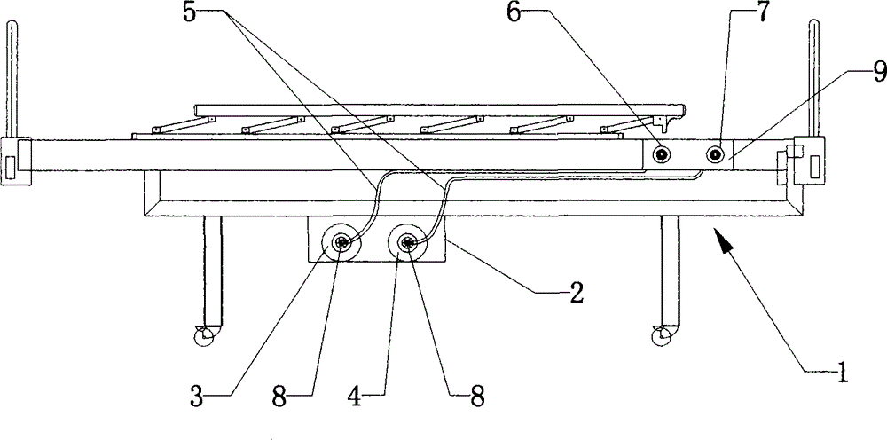
图1是本实用新型实施例所述的移动式中心供养、吸引医疗病床的结构示意图。Fig. 1 is a structural schematic diagram of the mobile center support and suction medical bed described in the embodiment of the present invention.
图中:In the picture:
1、床体;2、固定架;3、氧气瓶;4、负压瓶;5、不锈钢管;6、氧气终端;7、吸引终端;8、压力表;9、设备带。1. Bed body; 2. Fixed frame; 3. Oxygen bottle; 4. Negative pressure bottle; 5. Stainless steel tube; 6. Oxygen terminal; 7. Suction terminal; 8. Pressure gauge; 9. Equipment belt.
具体实施方式 Detailed ways
下面结合附图和实施例,对本实用新型的具体实施方式作进一步详细描述。以下实施例用于说明本实用新型,但不用来限制本实用新型的范围。Below in conjunction with accompanying drawing and embodiment, the specific embodiment of the utility model is described in further detail. The following examples are used to illustrate the utility model, but not to limit the scope of the utility model.
如图1所示,移动式中心供养、吸引医疗病床,包括床体1,所述床体1的底部设有固定架2,固定架2上分别设有氧气瓶3和负压瓶4,氧气瓶3和负压瓶4分别通过不锈钢管5连接氧气终端6和吸引终端7,不锈钢管5与氧气瓶3和负压瓶(4)的连接处分别设有压力表8,氧气终端6和吸引终端7设置在床体1顶部一端处的设备带9上。As shown in Figure 1, the mobile center supports and attracts medical beds, including a bed body 1, and the bottom of the bed body 1 is provided with a fixed frame 2, and the fixed frame 2 is respectively provided with an oxygen bottle 3 and a negative pressure bottle 4. The bottle 3 and the negative pressure bottle 4 are respectively connected to the oxygen terminal 6 and the suction terminal 7 through the stainless steel tube 5, and the joints of the stainless steel tube 5 and the oxygen bottle 3 and the negative pressure bottle (4) are respectively provided with a pressure gauge 8, the oxygen terminal 6 and the suction terminal The terminal 7 is arranged on the equipment belt 9 at one end of the top of the bed body 1 .
本实用新型的医用床结构简单,在原有的病床上增加氧气瓶、负压瓶、氧气终端和吸引终端,当病人需要时,直接将呼吸器插入氧气终端内就可以使用,生产成本低,适宜大范围推广应用。The medical bed of the utility model has a simple structure, and an oxygen bottle, a negative pressure bottle, an oxygen terminal and a suction terminal are added to the original hospital bed. When the patient needs it, the respirator can be used directly by inserting it into the oxygen terminal. Promote applications on a large scale.
以上所述仅是本实用新型的优选实施方式,应当指出,对于本技术领域的普通技术人员来说,在不脱离本实用新型技术原理的前提下,还可以做出若干改进和变型,这些改进和变型也应视为本实用新型的保护范围。The above is only a preferred embodiment of the utility model, it should be pointed out that for those of ordinary skill in the art, without departing from the technical principle of the utility model, some improvements and modifications can also be made. And modification should also be regarded as the protection scope of the present utility model.
Claims (1)
Priority Applications (1)
| Application Number | Priority Date | Filing Date | Title |
|---|---|---|---|
| CN2012200687725U CN202497360U (en) | 2012-02-29 | 2012-02-29 | Movable type central oxygen supply and aspiration medical ward bed |
Applications Claiming Priority (1)
| Application Number | Priority Date | Filing Date | Title |
|---|---|---|---|
| CN2012200687725U CN202497360U (en) | 2012-02-29 | 2012-02-29 | Movable type central oxygen supply and aspiration medical ward bed |
Publications (1)
| Publication Number | Publication Date |
|---|---|
| CN202497360U true CN202497360U (en) | 2012-10-24 |
Family
ID=47033992
Family Applications (1)
| Application Number | Title | Priority Date | Filing Date |
|---|---|---|---|
| CN2012200687725U Expired - Fee Related CN202497360U (en) | 2012-02-29 | 2012-02-29 | Movable type central oxygen supply and aspiration medical ward bed |
Country Status (1)
| Country | Link |
|---|---|
| CN (1) | CN202497360U (en) |
-
2012
- 2012-02-29 CN CN2012200687725U patent/CN202497360U/en not_active Expired - Fee Related
Similar Documents
| Publication | Publication Date | Title |
|---|---|---|
| CN204600951U (en) | Parturient nursing bed | |
| CN202497360U (en) | Movable type central oxygen supply and aspiration medical ward bed | |
| CN204542633U (en) | Multifunction nursing bed | |
| CN203089626U (en) | Oxygen generation nursing bed | |
| CN204106398U (en) | Multifunction nursing bed | |
| CN203252648U (en) | Elevation type electric bed used for magnetic resonance | |
| CN201366049Y (en) | Medical folding bed | |
| CN105193562A (en) | Multifunctional nursing bed | |
| CN203619797U (en) | Medical device combining nursing seat and sickbed | |
| CN202366069U (en) | Patient dining disk | |
| CN201603172U (en) | Disposable transfusion apparatus | |
| CN202908744U (en) | Device facilitating prostatic fluid taking of patients | |
| CN203598146U (en) | Hospital bed | |
| CN204246365U (en) | Patient moves bed apparatus | |
| CN202459580U (en) | Infusion support convenient to move | |
| CN201244146Y (en) | Suckling rack on bed head | |
| CN201551475U (en) | Sickbed provided with bedside table | |
| CN202459579U (en) | Convenient transfusion frame | |
| CN204562824U (en) | Antithrombotic equipment | |
| CN202184802U (en) | Supporting device convenient for patient to take prostatic fluid | |
| CN203042742U (en) | Multifunctional medical hospital bed | |
| CN201618036U (en) | Digestive internal medical sickbed | |
| CN201822986U (en) | Shelving device for end of rubber pipe | |
| CN201822981U (en) | Resting pad for facilitating nursing work | |
| CN203017477U (en) | Shoulder-back type dripping frame |
Legal Events
| Date | Code | Title | Description |
|---|---|---|---|
| C14 | Grant of patent or utility model | ||
| GR01 | Patent grant | ||
| C17 | Cessation of patent right | ||
| CF01 | Termination of patent right due to non-payment of annual fee |
Granted publication date: 20121024 Termination date: 20140229 |
|
| CF01 | Termination of patent right due to non-payment of annual fee |