CN202497211U - Liquid storage bottle having emergency-relief valve - Google Patents
Liquid storage bottle having emergency-relief valve Download PDFInfo
- Publication number
- CN202497211U CN202497211U CN2011203169973U CN201120316997U CN202497211U CN 202497211 U CN202497211 U CN 202497211U CN 2011203169973 U CN2011203169973 U CN 2011203169973U CN 201120316997 U CN201120316997 U CN 201120316997U CN 202497211 U CN202497211 U CN 202497211U
- Authority
- CN
- China
- Prior art keywords
- relief valve
- emergency
- emergency relief
- pressure system
- liquid storage
- Prior art date
- Legal status (The legal status is an assumption and is not a legal conclusion. Google has not performed a legal analysis and makes no representation as to the accuracy of the status listed.)
- Expired - Fee Related
Links
Images


Landscapes
- Media Introduction/Drainage Providing Device (AREA)
Abstract
A liquid storage bottle having an emergency-relief valve is provided, mainly comprising a liquid storage bottle body, an upper end bottle cover, a suction pipe, an air exhaust pipe, and the emergency-relief valve. The emergency-relief valve mainly consists of a valve core, a button and a valve body. By switching the valve core between two different operating positions, two states can be realized, i.e., a negative-pressure system can communicate with or be isolated from outside air. In an emergency, a doctor only needs to press down an emergency button, and then pressure releasing and negative-pressure system blocking can be realized at the same time, thereby preventing a defect that in traditional situations, when the emergency-relief valve is pressed down, only the pressure can be released, but the negative-pressure system can not be blocked.
Description
Technical field
This utility model relates to medical instruments field, is specifically related to the liquid containing bottle of band emergency relief valve in a kind of obstetrics and gynecology operation.
Background technology
The department of obstetrics and gynecology surgical drainage mainly is to utilize vacuum pump to produce negative pressure system now; Negative pressure system links to each other with a metal suction catheter through high-temperature sterilization; The metal suction catheter is inserted pregnant women's uterus; Utilize the suction that negative pressure system provides will be, thereby reach the purpose of termination of pregnancy attached to the embryonal tissue's sucking-off on the endometrium.
The emergency relief valve that suction pump is worn on the market now only has the function of relieving pressure; In operation process, in case of emergency all be to fall the pressure releasing in the negative pressure system earlier, if do not press the running that on and off switch stops vacuum pump this moment through emergency relief valve; Pump still can produce pull of vacuum; In a single day the hands of controlled discharge valve gets loose, and metal suction catheter inside can continue to be full of suction again, has certain hidden danger.
The utility model content
The purpose of this utility model provides a kind of liquid containing bottle with emergency relief valve, solves the hidden danger of the negative pressure system existence of this usual manner in the market,, make operation process safer.
The technical scheme of this utility model is achieved in that the liquid containing bottle of band emergency relief valve comprises liquid containing bottle bottle 1, upper end bottle cap 2, exhaust tube 3, suction catheter 4 and emergency relief valve 5.It is characterized in that; Emergency relief valve 5 is to connect constantly with atmosphere; Emergency relief valve 5 links together through needle roller 6 with spool 7, and spool 7 moves with horizontal direction through the spacing of stopper slot 10 only, is communicated with through a passage 9 between exhaust tube 3 and the emergency relief valve 5; Sealing ring 8 is positioned at the groove around the passage 9, and suction catheter 4 links together through the metal suction catheter of rubber or silica gel hose and operation end.Emergency relief valve is fixed on bottle cap inside, stretches out a red button in bottle cap outside, and through the lifting and press of button, spool 7 switches between two different working positions.
When button lifts, the inner and outside air partition of liquid containing bottle, the negative pressure system that vacuum pump produces is connected with operation end metal suction catheter, can carry out normal operation technique at this moment.When in case of emergency, to press button fall, liquid containing bottle inside and outside air are connected, and the negative pressure of bottle interior was released within several seconds to finish, thereby has realized the pressure releasing function.In this simultaneously,, do not had pressure in the operation end suction catheter yet, thereby realized stoping negative pressure system in operation end suction catheter, to continue to produce the probability of negative pressure simultaneously, guaranteed the safety of operation because whole negative pressure system and outside air are connected.
Description of drawings
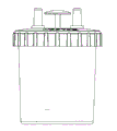
Fig. 1 is a front view
Fig. 2 is a vertical view
Fig. 3 is emergency relief valve A-A cutaway view when lifting
Fig. 4 is emergency relief valve A-A cutaway view when pressing
The specific embodiment
Be described further below in conjunction with the performance of accompanying drawing this utility model.
Like Fig. 3, the liquid containing bottle of band emergency relief valve comprises liquid containing bottle bottle 1, upper end bottle cap 2, exhaust tube 3, suction catheter 4 and emergency relief valve 5.It is characterized in that; Emergency relief valve 5 is to connect constantly with atmosphere; Emergency relief valve 5 links together through needle roller 6 with spool 7, and spool 7 moves with horizontal direction through the spacing of stopper slot 10 only, is communicated with through a passage 9 between exhaust tube 3 and the emergency relief valve 5; Sealing ring 8 is positioned at the groove around the passage 9; Suction catheter 4 links together through the metal suction catheter of rubber or silica gel hose and operation end, and a hole is arranged on upper end bottle cap 2, and bleeder valve button 5 stretches out the button of a redness in the bottle cap outside through this hole.
The liquid containing bottle of the band emergency relief valve that this utility model proposes is work like this; The negative pressure system that vacuum pump produces is communicated with exhaust tube 3, when the emergency relief valve button lift be on, during position as shown in Figure 3; Spool 7 is under the active force of needle roller 6; Side end face and sealing ring 8 tightly fit together, and this moment, passage 9 was sealed by spool 7 side end faces, was obstructed between exhaust tube 3 and the emergency relief valve 5; Negative pressure system is being performed the operation through suction catheter 4 at this moment. and produce negative pressure in the end metal suction catheter, can normally implement operation; Press when the emergency relief valve button to fall to being in the lower end, during position as shown in Figure 4, spool 7 moves to right under the active force of needle roller 6; Spool 7 side end faces and sealing ring were opened in 8 minutes, and this moment, passage 9 was opened, and was communicated with between exhaust tube 3 and the emergency relief valve 5; Because emergency relief valve 5 connects with atmosphere constantly; The negative pressure system that this moment, vacuum pump produced also connects with ambient atmosphere, and whole liquid containing bottle internal pressure is zero, even vacuum pump is still in work; The operation end metal suction catheter internal pressure that links to each other with suction catheter 4 also is zero, has guaranteed the safety of operation.
Claims (1)
1. liquid containing bottle with emergency relief valve; Comprise liquid containing bottle bottle (1), upper end bottle cap (2), exhaust tube (3), suction catheter (4), emergency relief valve (5); It is characterized in that; Emergency relief valve (5) and atmosphere are to connect constantly, and emergency relief valve (5) and spool (7) link together through needle roller (6), and spool (7) is through spacing the moving with horizontal direction of stopper slot (10) only; Be communicated with through a passage (9) between exhaust tube (3) and the emergency relief valve (5), sealing ring (8) is positioned at passage (9) groove on every side.
Priority Applications (1)
| Application Number | Priority Date | Filing Date | Title |
|---|---|---|---|
| CN2011203169973U CN202497211U (en) | 2011-08-24 | 2011-08-24 | Liquid storage bottle having emergency-relief valve |
Applications Claiming Priority (1)
| Application Number | Priority Date | Filing Date | Title |
|---|---|---|---|
| CN2011203169973U CN202497211U (en) | 2011-08-24 | 2011-08-24 | Liquid storage bottle having emergency-relief valve |
Publications (1)
| Publication Number | Publication Date |
|---|---|
| CN202497211U true CN202497211U (en) | 2012-10-24 |
Family
ID=47033845
Family Applications (1)
| Application Number | Title | Priority Date | Filing Date |
|---|---|---|---|
| CN2011203169973U Expired - Fee Related CN202497211U (en) | 2011-08-24 | 2011-08-24 | Liquid storage bottle having emergency-relief valve |
Country Status (1)
| Country | Link |
|---|---|
| CN (1) | CN202497211U (en) |
-
2011
- 2011-08-24 CN CN2011203169973U patent/CN202497211U/en not_active Expired - Fee Related
Similar Documents
| Publication | Publication Date | Title |
|---|---|---|
| CN203029684U (en) | Novel drainage device for medicine department | |
| CN202497211U (en) | Liquid storage bottle having emergency-relief valve | |
| CN208864893U (en) | A kind of medical treatment department of general surgery hepatobiliary drainage device | |
| CN203138604U (en) | Postoperative hemostasis device for anorectal department | |
| CN206587208U (en) | The drainage system of all seepages of anti-pipe | |
| CN209847933U (en) | Negative pressure suction connecting pipe joint | |
| CN202909164U (en) | Micro negative pressure drainage device for clinical medical | |
| CN215839394U (en) | Vaginal delivery bag type delivery assisting device | |
| CN216294828U (en) | Open pneumothorax first aid composite set | |
| CN210962240U (en) | Obstetrical amniotic fluid membrane rupture device | |
| CN203001522U (en) | Negative pressure drainage device | |
| CN202288975U (en) | Thoracic cavity closed type drainage tube | |
| CN203861755U (en) | Safe controlled silica gel negative pressure drainage ball | |
| CN203122566U (en) | Novel membrane breaking device | |
| CN202859258U (en) | Artificial rupture of fetal membrane device used for obstetrical department | |
| CN120477857B (en) | Hemostatic device for nursing of hematology department | |
| CN209033501U (en) | Disposable special syringe for glycerine enema | |
| CN209475227U (en) | A kind of internal medicine nursing drainage device | |
| CN208799297U (en) | A kind of medical gynemetrics's natural labor auxiliary device | |
| CN208958906U (en) | Portable handheld medical sputum aspirator | |
| CN208659995U (en) | A kind of abdominal drainage device | |
| LU508939B1 (en) | Pediatric Laryngeal Observation Device | |
| CN214712727U (en) | Uterus lifting device for vaginal sealing | |
| CN218793262U (en) | Thyroid puncture drainage device | |
| CN220141731U (en) | An obstetric and gynecological hemostatic device |
Legal Events
| Date | Code | Title | Description |
|---|---|---|---|
| C14 | Grant of patent or utility model | ||
| GR01 | Patent grant | ||
| CF01 | Termination of patent right due to non-payment of annual fee | ||
| CF01 | Termination of patent right due to non-payment of annual fee |
Granted publication date: 20121024 Termination date: 20160824 |