CN202497101U - Vertical pressure mop squeezing cleaning device - Google Patents
Vertical pressure mop squeezing cleaning device Download PDFInfo
- Publication number
- CN202497101U CN202497101U CN2011205119979U CN201120511997U CN202497101U CN 202497101 U CN202497101 U CN 202497101U CN 2011205119979 U CN2011205119979 U CN 2011205119979U CN 201120511997 U CN201120511997 U CN 201120511997U CN 202497101 U CN202497101 U CN 202497101U
- Authority
- CN
- China
- Prior art keywords
- stripper plate
- bracing
- strutting arrangement
- cleaning device
- pressure
- Prior art date
- Legal status (The legal status is an assumption and is not a legal conclusion. Google has not performed a legal analysis and makes no representation as to the accuracy of the status listed.)
- Expired - Fee Related
Links
- 238000004140 cleaning Methods 0.000 title claims abstract description 20
- XLYOFNOQVPJJNP-UHFFFAOYSA-N water Substances O XLYOFNOQVPJJNP-UHFFFAOYSA-N 0.000 claims abstract description 50
- 238000000034 method Methods 0.000 claims description 14
- 238000010276 construction Methods 0.000 claims description 3
- 238000005056 compaction Methods 0.000 claims description 2
- 238000001125 extrusion Methods 0.000 abstract description 13
- 230000000694 effects Effects 0.000 abstract description 3
- 238000004519 manufacturing process Methods 0.000 abstract description 3
- 239000004744 fabric Substances 0.000 description 3
- 230000006835 compression Effects 0.000 description 2
- 238000007906 compression Methods 0.000 description 2
- 238000005516 engineering process Methods 0.000 description 2
- 239000000463 material Substances 0.000 description 2
- 230000009286 beneficial effect Effects 0.000 description 1
- 230000015572 biosynthetic process Effects 0.000 description 1
- 238000009835 boiling Methods 0.000 description 1
- 230000007812 deficiency Effects 0.000 description 1
- 230000002950 deficient Effects 0.000 description 1
- 210000001624 hip Anatomy 0.000 description 1
- 239000007769 metal material Substances 0.000 description 1
- 238000003825 pressing Methods 0.000 description 1
- 239000010865 sewage Substances 0.000 description 1
Images


Landscapes
- Cleaning Implements For Floors, Carpets, Furniture, Walls, And The Like (AREA)
Abstract
A vertical pressure mop squeezing cleaning device has two extrusion sheets. Lower ends of the extrusion sheets are directly interconnected or are connected through a third mechanism so as to form a hinge-shaped relative swing mechanism. The extrusion sheets are connected with a support device. The support device restricts upper ends of the extrusion sheets to slide or swing towards directions of extrusion surfaces and the lower ends of the extrusion sheets. During usage, a mop head is extruded downwards and vertically on a joint of the lower ends of the extrusion sheets. When the joint of the lower ends of the extrusion sheets receives downward pressure, the extrusion sheets are closed up and generate an extrusion force so that excessive water in the mop can be extruded. The device of the utility model is suitable for the traditional mops with a common round head and a wide head. Operation is convenient. An effect of squeezing water is good. A structure is simple. Production cost is low and the device is easy to be popularized.
Description
Technical field
The utility model relates to a kind of mop water squeezing cleaning device, particularly pressure at right angle mop water squeezing cleaning device.
Background technology
Mopping the floor is the housework that often need do in the daily life, and we need clean mop and extrude moisture too much in the mop when mopping the floor, and stubborn not only labour intensity is big if go with hand, nor health.So occurred on the market now much can water squeezing mop; These outstanding inventions have solved this problem well; But often the comparatively complicated cost of structure is also than higher for this mop, and mop itself also is consumptive, increases purchase cost if buy again after damaging; And can only adopt sponge or other materials as the cleaning face, result of use is not as traditional pier cloth mop.Also having one type of invention is the cleaning squeezing water that is applied to traditional pier cloth mop; Foot-operated water squeezing wherein arranged with put into cylinder and directly press down mode; The device of foot-operated water squeezing has complex structure, shortcoming that fragile cost is high equally; Put into cylinder and directly press down the device of mode because pressing body is a mop rod and adopt, sectional area is little, and squeezing effect is limited.
Summary of the invention
Defective and deficiency to indication in " background technology "; The pressure at right angle mop water squeezing cleaning device that the utility model relates to is applicable to the traditional pier cloth mop cheap, that result of use is good; And the utility model is simple in structure, production cost is low, easy to operate, water squeezing is effective, has solved the problems referred to above well.
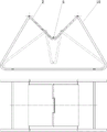
Technical scheme: pressure at right angle mop water squeezing cleaning device mainly contains two stripper plates, and the stripper plate lower end directly interconnects or connects the relative swing mechanism that (increasing a plate or hinge means such as the centre) forms the hinge shape through the 3rd mechanism; Stripper plate is connected with bracing or strutting arrangement, and bracing or strutting arrangement restriction stripper plate upper end extreme direction under compressive plane and stripper plate slides or swing.
The annexation of stripper plate and bracing or strutting arrangement does; The back side of stripper plate has the ramped shaped projection of self compaction plate upper end to stripper plate lower end and the inclination of compressive plane direction; Bracing or strutting arrangement has supporting pile at correspondence position; Support the stripper plate back side, the inclined-plane of stripper plate projection can reciprocatingly slide on supporting pile; Or bracing or strutting arrangement has supporting pile at correspondence position, supports the stripper plate back side, and the stripper plate back side can reciprocatingly slide on supporting pile; Or have supporting pile on the stripper plate, and it is from the stripper plate back side to compressive plane and the guide rail that extreme direction tilts under the stripper plate that bracing or strutting arrangement has direction, the supporting pile of stripper plate upper end is enough to reciprocatingly slide along guide rail; Or stripper plate upper end is connected with swing arm on the bracing or strutting arrangement, and swing arm can be swung by extreme direction under compressive plane and stripper plate; Or directly be connected with the bracing or strutting arrangement of shelf-like on the stripper plate, bracing or strutting arrangement and stripper plate attaching parts can be swung by extreme direction under compressive plane and stripper plate; The column structure that supporting pile adopts smooth column structure or external diameter to be equipped with roller.Bracing or strutting arrangement can limit that stripper plate upper end extreme direction under compressive plane and stripper plate slides or the structure of swing also have a lot, as long as satisfy the structural strength requirement and the range of movement requirement all can be applicable to the utility model.
On the stripper plate or between stripper plate and the supporting construction flexible member is installed; Make stripper plate when not being under pressure, can automatically revert to original position; Be convenient to the continuous several times extruding; As adding torsionspring settling under the place of interconnecting, stripper plate lower end on compression spring or the axle in the junction, perhaps connect the tensile elasticity element at the stripper plate back side, perhaps utilize the elasticity of support own during for support when supporter.
Traditional round end mop mop mop root binding position is generally thicker than mop rod; And other a kind of wide wooden or plastic material that mop mop root is a strip; In stripper plate extruding mop mop; Stripper plate can be expressed to mop root and mop rod, and stripper plate can not further be pushed.Point midway to lower end, stripper plate upper end point midway direction is processed with the semicircle groove of somewhat larger in diameter in conventional mop rod diameter so the utility model is in the compressive plane upper edge of stripper plate, and mop rod is not squeezed in extrusion process; Expand as common round end mop mop root binding position diameter in the lower end diameter of semicircle groove, round end mop root is not squeezed in extrusion process; Be processed with the cuboid groove with the semicircle groove vertical direction in the lower end of semicircle groove, the length and width of groove are slightly larger than the length and width of wide mop mop root shape, and wide mop root is not squeezed in extrusion process, thereby improve the squeezing effect to mop; On the compressive plane of stripper plate, be processed with the corrugated texture and on stripper plate, process some through holes, thereby strengthen the frictional force of stripper plate, and accelerate the discharge that squeezes the water out.
Bracing or strutting arrangement can be water tank, tank, bucket or support, and one side has discharge outlet in the bottom of water tank, tank or bucket, and the discharge outlet place is equipped with foot-operated draining valve, and foot-operated draining valve connects drainpipe; Devices such as wheel, handle dividing plate can be set on water tank, tank or bucket, make things convenient for this device to use in each occasion.
During use; Mophead is vertically pushed to the place of interconnecting, stripper plate lower end down; The place of interconnecting receives downward pressure when the stripper plate lower end, and extruding force is extruded mop mop excess moisture thereby stripper plate is drawn close generation each other, and can regard as with the place of interconnecting, stripper plate lower end this moment is fulcrum; The mop mop is that stress point and stripper plate upper end is the lever of the point of application, so stripper plate water squeezing process can be more laborsaving.When the utility model uses water tank, tank or bucket as bracing or strutting arrangement; The tap of fetching boiling water is filled to water tank, tank or bucket to correct position; Hand-held mop rod vertically pushes mophead to the place of interconnecting, stripper plate lower end down repeatedly; Mophead immersed in the water and was squeezed repeatedly and can effectively wash the dirt on the mop this moment; Tramp with one's feet after cleaning and step on draining valve, once more vertically to the extruding of the place of interconnecting, stripper plate lower end, can extrude mop mop excess moisture after the sewage discharge in water tank, tank or the bucket is clean.
The beneficial effect of the utility model is: the utility model is applicable to widely used common mop, and is easy to operate, water squeezing is effective, simple in structure, production cost is low is convenient to popularize, thereby reduces people's housework intensity, improves people's comfortable life degree.
Description of drawings: Figure of description Fig. 1-5 is the view of the utility model embodiment 1-5; Wherein front view is a full sectional view; The internal structure and the annexation that have reflected embodiment, two-dot chain line are the extreme position profile of stripper plate, have reflected the range of movement of stripper plate; Vertical view has reflected shape and the annexation that has reflected stripper plate, bracing or strutting arrangement from depression angle; View is mainly expressed stripper plate and is connected and movement relation with the various of supporting construction, so omitted texture and other architectural features on the stripper plate; In Figure of description, relate to axle and expressed the outline of axle, and omit the interior profile in the hole of knowing clearly with (like the axle of the two stripper plate junctions) with dashed lines that cooperates in hole.
The title of each parts in the Figure of description: supporting pile, (8) guide rail, (9) swing arm, (10) support of (1) water tank, (2) stripper plate, the stake of (3) card, (4) supporting pile, (5) rotating shaft, (6) ramped shaped projection, (7) band roller.
The specific embodiment:
Claims (10)
1. pressure at right angle mop water squeezing cleaning device is made up of bracing or strutting arrangement, stripper plate, it is characterized by, and the stripper plate lower end directly interconnects or be connected to form through the 3rd mechanism the relative swing mechanism of hinge shape; Stripper plate is connected with bracing or strutting arrangement, and bracing or strutting arrangement restriction stripper plate upper end extreme direction under compressive plane and stripper plate slides or swing.
2. pressure at right angle mop water squeezing cleaning device according to claim 1; It is characterized by; The back side of stripper plate has the ramped shaped projection of self compaction plate upper end to stripper plate lower end and the inclination of compressive plane direction; Bracing or strutting arrangement has supporting pile at correspondence position, supports the stripper plate back side, and the inclined-plane of stripper plate projection can reciprocatingly slide on supporting pile.
3. pressure at right angle mop water squeezing cleaning device according to claim 1 is characterized by, and bracing or strutting arrangement has supporting pile at correspondence position, supports the stripper plate back side, and the stripper plate back side can reciprocatingly slide on supporting pile.
4. pressure at right angle mop water squeezing cleaning device according to claim 1; It is characterized by; The stripper plate upper end has supporting pile, and it is from the stripper plate back side to compressive plane and the guide rail of stripper plate lower end inclination that bracing or strutting arrangement has direction, and the supporting pile of stripper plate upper end is enough to reciprocatingly slide along guide rail.
5. pressure at right angle mop water squeezing cleaning device according to claim 1 is characterized by, and stripper plate upper end is connected with swing arm on the bracing or strutting arrangement, and swing arm can be swung by extreme direction under compressive plane and stripper plate.
6. pressure at right angle mop water squeezing cleaning device according to claim 1 is characterized by, and the stripper plate upper end directly is connected with the bracing or strutting arrangement of shelf-like, and bracing or strutting arrangement and stripper plate attaching parts can extreme direction swings under compressive plane and stripper plate.
7. pressure at right angle mop water squeezing cleaning device according to claim 1 is made up of bracing or strutting arrangement, stripper plate, it is characterized by the column structure that supporting pile adopts smooth column structure or external diameter to be equipped with roller.
8. pressure at right angle mop water squeezing cleaning device according to claim 1 is characterized by, and on the stripper plate or between stripper plate and the supporting construction flexible member is installed, and makes stripper plate when not being under pressure, can automatically revert to original position.
9. pressure at right angle mop water squeezing cleaning device according to claim 1 is characterized by, and point midway to lower end, stripper plate upper end point midway direction is processed with semicircle groove in the compressive plane upper edge of stripper plate; On the compressive plane of stripper plate, be processed with the corrugated texture and on stripper plate, process some through holes.
10. pressure at right angle mop water squeezing cleaning device according to claim 1 is characterized by, and bottom one side of making water tank, tank or the bucket of bracing or strutting arrangement has discharge outlet, and the discharge outlet place is equipped with foot-operated draining valve, and foot-operated draining valve connects drainpipe.
Priority Applications (1)
| Application Number | Priority Date | Filing Date | Title |
|---|---|---|---|
| CN2011205119979U CN202497101U (en) | 2011-12-09 | 2011-12-09 | Vertical pressure mop squeezing cleaning device |
Applications Claiming Priority (1)
| Application Number | Priority Date | Filing Date | Title |
|---|---|---|---|
| CN2011205119979U CN202497101U (en) | 2011-12-09 | 2011-12-09 | Vertical pressure mop squeezing cleaning device |
Publications (1)
| Publication Number | Publication Date |
|---|---|
| CN202497101U true CN202497101U (en) | 2012-10-24 |
Family
ID=47033736
Family Applications (1)
| Application Number | Title | Priority Date | Filing Date |
|---|---|---|---|
| CN2011205119979U Expired - Fee Related CN202497101U (en) | 2011-12-09 | 2011-12-09 | Vertical pressure mop squeezing cleaning device |
Country Status (1)
| Country | Link |
|---|---|
| CN (1) | CN202497101U (en) |
Cited By (3)
| Publication number | Priority date | Publication date | Assignee | Title |
|---|---|---|---|---|
| CN103156561A (en) * | 2011-12-09 | 2013-06-19 | 刘丰 | Vertical pressure water-squeezing and cleaning device for mop |
| CN103156561B (en) * | 2011-12-09 | 2016-12-14 | 刘丰 | Pressure at right angle mop water-expelling cleans device |
| CN111110129A (en) * | 2019-09-20 | 2020-05-08 | 胡国云 | Collodion working head water squeezing device |
-
2011
- 2011-12-09 CN CN2011205119979U patent/CN202497101U/en not_active Expired - Fee Related
Cited By (4)
| Publication number | Priority date | Publication date | Assignee | Title |
|---|---|---|---|---|
| CN103156561A (en) * | 2011-12-09 | 2013-06-19 | 刘丰 | Vertical pressure water-squeezing and cleaning device for mop |
| CN103156561B (en) * | 2011-12-09 | 2016-12-14 | 刘丰 | Pressure at right angle mop water-expelling cleans device |
| CN111110129A (en) * | 2019-09-20 | 2020-05-08 | 胡国云 | Collodion working head water squeezing device |
| CN111110129B (en) * | 2019-09-20 | 2024-05-17 | 胡国云 | Collodion working head water squeezing device |
Similar Documents
| Publication | Publication Date | Title |
|---|---|---|
| CN204293074U (en) | A kind of mop being convenient to water squeezing | |
| CN202497101U (en) | Vertical pressure mop squeezing cleaning device | |
| CN201775599U (en) | Mop and foot operated mop water squeezing and holding device | |
| CN103156561A (en) | Vertical pressure water-squeezing and cleaning device for mop | |
| CN103156561B (en) | Pressure at right angle mop water-expelling cleans device | |
| CN209136480U (en) | One kind is exempted to hand-wash mop device | |
| CN202636857U (en) | Folding-type mop | |
| CN202408794U (en) | Mop wringing device | |
| CN108464795A (en) | A kind of mop cleaning device | |
| CN201691880U (en) | Water squeezing device and mopping barrel provided with water squeezing device | |
| CN211243219U (en) | A hand-free mop | |
| CN208404441U (en) | Rubber cotton flat drag bucket | |
| CN201389000Y (en) | Mop dehydrating barrel | |
| CN201524049U (en) | Mop drainer | |
| CN206228308U (en) | A kind of pedal-powered mop squeezing water | |
| CN201388999Y (en) | Dewatering bucket for mop | |
| CN201147289Y (en) | Washing and dewatering tub for mop | |
| CN111513638A (en) | A shared squeeze bucket for flat mop and column mop | |
| CN2432888Y (en) | Pedal water squeezing bucket for mop | |
| CN211484440U (en) | Cotton mop squeezing device | |
| CN201492371U (en) | Adjustable pre-wet glass cleaner | |
| CN209136496U (en) | The swinging structure of pressure roller in a kind of mop washing barrel | |
| CN201008541Y (en) | Water wringing pipe of colloidine mop head | |
| CN205083404U (en) | Mop is put down to multi -functional crowded water of hand washing of exempting from with dragging | |
| CN207970065U (en) | Extruding flat mop burnisher with handle |
Legal Events
| Date | Code | Title | Description |
|---|---|---|---|
| C14 | Grant of patent or utility model | ||
| GR01 | Patent grant | ||
| CF01 | Termination of patent right due to non-payment of annual fee |
Granted publication date: 20121024 Termination date: 20151209 |
|
| EXPY | Termination of patent right or utility model |