CN202494855U - Display device - Google Patents
Display device Download PDFInfo
- Publication number
- CN202494855U CN202494855U CN201220056508XU CN201220056508U CN202494855U CN 202494855 U CN202494855 U CN 202494855U CN 201220056508X U CN201220056508X U CN 201220056508XU CN 201220056508 U CN201220056508 U CN 201220056508U CN 202494855 U CN202494855 U CN 202494855U
- Authority
- CN
- China
- Prior art keywords
- image
- display device
- catoptron
- projector
- projection screen
- Prior art date
- Legal status (The legal status is an assumption and is not a legal conclusion. Google has not performed a legal analysis and makes no representation as to the accuracy of the status listed.)
- Expired - Fee Related
Links
- 230000003287 optical effect Effects 0.000 claims abstract description 34
- 238000003709 image segmentation Methods 0.000 claims abstract description 9
- 238000000034 method Methods 0.000 claims description 12
- 230000008569 process Effects 0.000 claims description 12
- 230000008878 coupling Effects 0.000 claims description 8
- 238000010168 coupling process Methods 0.000 claims description 8
- 238000005859 coupling reaction Methods 0.000 claims description 8
- 230000004888 barrier function Effects 0.000 claims description 6
- 238000003909 pattern recognition Methods 0.000 claims description 6
- 230000000694 effects Effects 0.000 abstract description 5
- 230000008901 benefit Effects 0.000 abstract description 2
- 238000003384 imaging method Methods 0.000 description 5
- 238000009434 installation Methods 0.000 description 3
- 230000001105 regulatory effect Effects 0.000 description 3
- 230000002950 deficient Effects 0.000 description 2
- 238000010586 diagram Methods 0.000 description 2
- 230000004927 fusion Effects 0.000 description 2
- 239000004973 liquid crystal related substance Substances 0.000 description 2
- 238000005070 sampling Methods 0.000 description 2
- 229910000838 Al alloy Inorganic materials 0.000 description 1
- 240000007594 Oryza sativa Species 0.000 description 1
- 235000007164 Oryza sativa Nutrition 0.000 description 1
- 230000000295 complement effect Effects 0.000 description 1
- 230000007423 decrease Effects 0.000 description 1
- 230000018109 developmental process Effects 0.000 description 1
- 238000005516 engineering process Methods 0.000 description 1
- 239000011521 glass Substances 0.000 description 1
- 230000003760 hair shine Effects 0.000 description 1
- 239000000463 material Substances 0.000 description 1
- 230000007246 mechanism Effects 0.000 description 1
- 238000005065 mining Methods 0.000 description 1
- 238000000465 moulding Methods 0.000 description 1
- 230000002035 prolonged effect Effects 0.000 description 1
- 235000009566 rice Nutrition 0.000 description 1
- 238000000926 separation method Methods 0.000 description 1
- 230000000007 visual effect Effects 0.000 description 1
Images

Landscapes
- Transforming Electric Information Into Light Information (AREA)
Abstract
The utility model discloses a display device, which comprises a signal input source, an image processing device connected with the signal input source, an image output device connected with the image processing device, wherein the image processing device comprises an image segmentation processing device connected with the signal input source, and an image combination processing device connected with the image output device. The display device is characterized in that: the image output device comprises an optical projection screen, and at least two sets of projection devices arranged behind the optical projection screen, wherein each of the projection device comprises a projector and two reflecting mirrors; and projection directions of the projectors are in oblique crossing with the optical projection screen. The display device of the utility model has the advantages of seamless spliced images, even and perfect display, good display effect, small overall volume, thin thickness, high attractiveness in appearance, small occupied space, good overall heat dissipating effect, low operating temperature, and long service life of the device.
Description
Technical field
The utility model relates to a kind of display device, relates in particular to the seamless spliced imaging display device of a kind of thin type optics.
Background technology
Along with socio-economic development, oversize display wall, the particularly display area application demand greater than the display wall of 3X1.5 rice is increased, the liquid crystal commonly used at present or the display size of plasm TV are 108 " to the maximum.In the oversize application scenario; People use the spliced display wall of liquid crystal or optical projection mode mostly; Spliced display wall is spliced by several LCD TV unit or optical projection display unit; Can accomplish that oversize shows, but have the physics splicing seams, the splicing seams of general LCD TV unit is 5.3 ~ 7.3mm; The splicing seams of optical projection unit is 0.5 ~ 1.0mm.Because the existence of splicing seams causes the shortcoming of visual effect when showing large scale view picture picture, and does not remedy means technically at present preferably.The solution that another kind satisfies oversize demonstration demand is to adopt projector to add projection screen; Like the patent No. is that 200420041588 Chinese patent discloses a kind of seamless splicing large screen display device; Form seamless fusion display system through the mode of the seamless fusion of computer graphical; Can solve the image vision shortcoming that above-mentioned physics splicing seams causes, having defective is this projection imaging mode has surround lighting when front projection the problem that influences, in the place that indoor light becomes clear or has daylight to penetrate; The contrast of imaging picture sharply descends, even adopt the high-brightness projection machine still can't better remedy; Same, adopt this imaging mode display device when back projection to have bigger thickness, it is big to take up room, and uses inconvenience, does not still have the mode that solves this defective fully at present.
The utility model content
The utility model provides a kind of viewing effect good thin type optics joining image-forming display device for solving the prior art problem.
The technical scheme of the utility model is: a kind of display device; Comprise signal input sources; The image processing apparatus that is connected with this signal input sources; And the image output device that is connected with said image processing apparatus, said image processing apparatus comprises the image segmentation treating apparatus that is connected with said signal input sources, and the image joining process device that is connected with said image output device; It is characterized in that: said image output device comprises the optical projection screen, and at least two covers are arranged at the projection arrangement at said optical projection screen rear, and said projection arrangement comprises projector and two catoptrons; The projecting direction of said projector and said optical projection screen oblique.
Display device seamless spliced, promptly there is not the physics splicing seams in the display part of display device; The image segmentation treating apparatus is cut apart original image according to the quantity and the position of projection arrangement; And the image after will cutting apart is delivered to the respective projection device through image joining process device; Between the image of adjacent projections device the overlapping region is set, view data is passed through the image joining process, the brightness and the colourity of overlapping region, overlapping back are consistent with original image again; The setting of two catoptrons can make the thickness of display device reduce greatly keeping the constant low required horizontal range of light path of prerequisite decline of projection imaging light path required separation distance, reaches the thin type effect.Projection arrangement adopts the mounting means from axial projection, the projecting direction of projector and optical projection screen oblique, i.e. and projecting direction and optical projection screen out of plumb further reduce the thickness of display device.
As preferably, said projection arrangement comprises projector and two catoptrons, and the quantity of said projection arrangement is even number, and the horizontal middle spindle mirror image of the said relatively optical projection screen of said projection arrangement distributes.The projection arrangement that mirror image distributes can further reduce the thickness of display device.
As preferably, said projector tilts to be installed in the said display device.Because the top of display device is equipped with a cover projection arrangement; Therefore the volume of the viewing area top device portion of display device is bigger; Cause the housing at display device top too high; Influence the good looking appearance degree of display device, the projector that tilts to install can further reduce the thickness of display device, is easy to that also the shell upper of display device is carried out moulding simultaneously and beautifies.
As preferably, said image processing apparatus also comprises pick-up unit, and said pick-up unit comprises the camera head that is arranged at said optical projection screen one side.The camera head that is in optical projection screen one side is monitored the picture that different projection arrangements project; As having brightness and colourity difference between these pictures; Then view data is adjusted; The picture brightness that makes all projection arrangements project is consistent with colourity, and whole picture brightness and colourity behind the joint are even.
As preferably, said camera head comprises the branch image pick-up device that is arranged at said projector one side, and the total image pick-up device that is arranged at said optical projection screen rear.
As preferably, said total image pick-up device comprises at least two sampled points, and the quantity of said sampled point is identical with the quantity of said projection arrangement, and the position of sampled point is positioned at the picture center that said projection arrangement is projected to the optical projection screen.
Divide image pick-up device to be used to monitor the picture after cutting apart, whether parameters such as the picture brightness that each projection arrangement projects, colourity are even, and total image pick-up device is used to monitor the picture behind the joint; Whether parameters such as the picture brightness that different projection arrangements project, colourity are consistent; When parameters such as the brightness of picture, colourity occur inhomogeneous, during situation such as consistance difference, through regulating image processing apparatus; And adjust the projection picture of projector with this, the frame parameter uniformity after keeping engaging.
As preferably, said display device also comprises shell, and the inside surface of this shell is a black; Said shell is provided with air vent.Display device adopts the rear-projection mode; Simultaneously equipment such as projector are all put into the shell of black inside surface; The external ambient light of blocking-up greatly reduces the internal light diffuse reflection to the interference that picture causes simultaneously to the influence of projecting light path fully, makes picture clean; Projection arrangement work the time will produce great amount of heat, and air vent can in time be discharged these heats, greatly reduce the temperature of projection arrangement when working, and prolong the life-span of projection arrangement.
As preferably, said air vent is provided with light barrier.The place that display device is used often has very complex environment light; Display device can be considered light pollution, and these surround lightings very likely get into along the air vent on the shell, and further disturb the light path of projection arrangement; Reduce the image quality of picture; Light barrier is used to stop that external environment light gets into through air vent, makes surround lighting can not exert an influence to the light path of projection, the image quality of further purifying.
As preferably, said catoptron is trapezoidal, comprises first catoptron and second catoptron; Four jiaos of said first catoptron are provided with microscler bolt hole, are provided with bolt in this bolt hole, and first catoptron is connected to fixed head through said bolt, and said fixed head is fixedly set on the said support; The long limit of said second catoptron is fixedly connected on an end of brace; The other end of this brace is provided with elongated hole; Brace is through on this elongated hole connection and the said support; The minor face of said second catoptron is connected with said support through web member, is provided with buffer spring in this web member.The position of first catoptron and second catoptron and angle all can be carried out 6 directions of X, Y, Z axle through fixed sturcture and regulated, and are convenient to the picture that setter goes out projector projects and accurately are adjusted to the position that needs on the optical projection screen; The display device of large-size screen monitors is installed on the more places of flow of the people such as market, large conference room mostly, and these places are the environment more complicated often, and the area of second catoptron is bigger; Making the used material of catoptron is glass; More frangible, therefore buffer spring is set at the minor face place of second catoptron, protected second catoptron effectively; Make it in complex environment, to be difficult for being damaged, prolonged the life-span of second catoptron greatly.
In sum, the utlity model has following advantage:
1, image is seamless spliced, uniform display, perfection, and display effect is good;
2, overall volume is little, thin thickness, and the good looking appearance degree is good, and it is little to take up room;
3, integral heat sink is effective, and running temperature is low, and equipment life is long.
Description of drawings
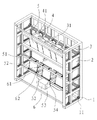
Fig. 1 is the utility model embodiment one inner structure synoptic diagram;
Fig. 2 is the utility model embodiment one shell mechanism synoptic diagram;
Fig. 3 is the scheme of installation of Fig. 1 and Fig. 2;
Fig. 4 is the utility model embodiment two projector scheme of installations.
Among the figure, 1, support, 11, hornblock, 2, the optical projection screen, 3, projector; 31, projector, 32, following projector, 4, first catoptron, 41, fixed head, 5, second catoptron; 51, brace, 52, elongated hole, 54, buffer spring, 6, master controller, 61, divide image pick-up device; 62, total image pick-up device, 7, shell, 71, air vent, 72, light barrier.
Embodiment
With embodiment the utility model is described further below.
Embodiment one:
A kind of display device like Fig. 1,2, shown in 3, comprises support 1, and the section bar that support 1 is processed by aluminium alloy constitutes, and the joint portion adopts hornblock 11 to be fixedly connected; Support 1 front end is provided with optical projection screen 2, and support 1 upper end has been horizontally disposed with three projector 3, is projector 31; Support 1 lower end has been horizontally disposed with three projector 3; Be following projector 32, projector 31 and of the center line up and down mirror image distribution of following projector 32 along optical projection screen 2, projector 3 is connected on the support 1 through bolt; Display device also is provided with first catoptron 4 and second catoptron 5; First catoptron 4 and second catoptron 5 are trapezoidal, and four jiaos of first catoptron 4 are provided with microscler bolt hole, are provided with bolt in this bolt hole; First catoptron 4 is connected to fixed head 41 through bolt, and fixed head 41 is fixedly set on the support 1; The long limit of second catoptron 5 is fixedly connected on an end of brace 51; The other end of this brace 51 is provided with elongated hole 52; Brace 51 is through on these elongated hole 52 connections and the support 1; The minor face of second catoptron 5 is connected with support 1 through web member, is provided with buffer spring 54 in this web member; Also be provided with master controller 6 in the support 1; This master controller 6 comprises the signal input sources that is connected with the outside; Signal input sources is connected with the image segmentation treating apparatus; The image segmentation treating apparatus is connected with six image joining process devices, and six image joining process devices are connected with six projector 3 respectively; One side of each projector 3 is provided with corresponding minute image pick-up device 61; Divide image pick-up device 61 to be connected with image joining process device; Center, optical projection screen 2 rear also is provided with the total image pick-up device 62 that is connected with the image coupling device, and total image pick-up device 62 has six sampled points, and these six sampled points lay respectively at the picture center that six projector 3 project; Be provided with pattern recognition device in the image joining process device, and the image adjustment device that is connected with pattern recognition device; Support 1 also is provided with shell 7, and the inside surface of shell 7 is close to the lateral surface of support 1, and the inside surface of shell 7 is black, has air vent 71 on the shell 7, and the inboard of air vent 71 is provided with light barrier 72.
During installation; The position of adjustment projector 3 and catoptron; The picture that makes projector 3 project shines fully in first catoptron 4; And through shining in optical projection screen 2 assigned addresses after first catoptron 4 and 5 reflections of second catoptron, the picture edge of adjacent projections appearance 3 projections is provided with the overlapping region successively, and all overlapping region width equate.
During work; Picture signal is delivered to display device from signal input sources; The image segmentation treating apparatus is evenly divided into six with the picture signal that receives according to the diverse location of different projector 3, and has certain overlapping region between the image after adjacent cutting apart, and the image after cutting apart is delivered to the image coupling device; Attenuation processing is carried out in overlapping region in the image after the image coupling device will be cut apart; Image after will handling then is delivered to projector 3, and through shining in optical projection screen 2 assigned addresses after first catoptron 4 and 5 reflections of second catoptron, the overlapping region decay of the picture of adjacent projections appearance 3 projections is complementary successively for the picture that projector 3 projects; The brightness of image equates with original brightness behind lap over, the synthetic image that does not have the slit on optical projection screen 2.
Meanwhile; Total 62 pairs of six sampled points of image pick-up device are sampled with certain frequency simultaneously; Divide the picture of 61 pairs of homolographic projection appearance of image pick-up device, 3 projections to sample; And sampled result is delivered to the image coupling device, and the pattern recognition device in the image coupling device is discerned the image of sampling, and whether the image of analyzing the different mining sampling point is consistent in parameters such as brightness, colourities; Then homolographic projection appearance 3 is regulated as inconsistent, finally made uniform display on the optical projection screen 2, perfect image through the image adjustment device.
Embodiment two:
A kind of display device comprises support 1, and support 1 front end is provided with optical projection screen 2; Three projector 3 have been horizontally disposed with on the support 1; Be provided with first catoptron, 4, the first catoptrons 4 between projector 3 and the optical projection screen 2 and be fixedly set on the support 1 through screw bolt and nut, a side of projector 3 is provided with second catoptron 5; Second catoptron 5 is fixedly set on the support 1 through the scalable web member, and first catoptron 4 and second catoptron 5 are trapezoidal; Also be provided with the signal input sources that is connected with the outside in the support 1, signal input sources is connected with the image segmentation treating apparatus, and the image segmentation treating apparatus is connected with three image joining process devices, and three image joining process devices are connected with three projector 3 respectively; One side of each projector 3 is provided with corresponding minute image pick-up device 61; Divide image pick-up device 61 to be connected with image joining process device; Be provided with pattern recognition device and image comparison device in the image joining process device, and the image adjustment device that is connected with the image comparison device with pattern recognition device respectively; Support 1 also is provided with shell 7, and the inside surface of shell 7 is close to the lateral surface of support 1, and the inside surface of shell 7 is black, has air vent 71 on the shell 7, and the inboard of air vent 71 is provided with light barrier 72.
Claims (10)
1. display device; Comprise signal input sources; The image processing apparatus that is connected with this signal input sources; And the image output device that is connected with said image processing apparatus, said image processing apparatus comprises the image segmentation treating apparatus that is connected with said signal input sources, and the image joining process device that is connected with said image output device; It is characterized in that: said image output device comprises the optical projection screen, and at least two covers are arranged at the projection arrangement at said optical projection screen rear, and said projection arrangement comprises projector and catoptron; The projecting direction of said projector and said optical projection screen oblique.
2. according to the said display device of claim 1, it is characterized in that: said projection arrangement comprises projector and two catoptrons, and the quantity of said projection arrangement is even number, and the horizontal middle spindle mirror image of the said relatively optical projection screen of said projection arrangement distributes.
3. according to the said display device of claim 1, it is characterized in that: said projector tilts to be installed in the said display device.
4. according to the said display device of claim 1, it is characterized in that: said image processing apparatus also comprises pick-up unit, and said pick-up unit comprises the camera head that is arranged at said optical projection screen one side.
5. according to the said display device of claim 4; It is characterized in that: said camera head comprises the branch image pick-up device that is arranged at said projector one side and is connected with the image coupling device, and the total image pick-up device that is arranged at said optical projection screen rear and is connected with the image coupling device; Also be provided with respectively the pattern recognition device that is connected with total image pick-up device with minute image pick-up device in the said image coupling device, and the image adjustment device that is connected with projector respectively.
6. according to the said display device of claim 5; It is characterized in that: said total image pick-up device comprises at least two sampled points; The quantity of said sampled point is identical with the quantity of said projection arrangement, and the position of sampled point is positioned at the picture center that said projection arrangement is projected to the optical projection screen.
7. according to the said display device of claim 1, it is characterized in that: said display device also comprises shell, and the inside surface of this shell is a black; Said shell is provided with air vent.
8. according to the said display device of claim 7, it is characterized in that: said air vent is provided with light barrier.
9. according to the said display device of claim 1, it is characterized in that: said display device comprises support.
10. according to the said display device of claim 9, it is characterized in that: said catoptron is trapezoidal, comprises first catoptron and second catoptron; Four jiaos of said first catoptron are provided with bolt hole, are provided with bolt in this bolt hole, and first catoptron is connected to fixed head through said bolt, and said fixed head is fixedly set on the said support; The long limit of said second catoptron is fixedly connected on an end of brace; The other end of this brace is provided with elongated hole; Brace is through on this elongated hole connection and the said support; The minor face of said second catoptron is connected with said support through web member, is provided with buffer spring in this web member.
Priority Applications (1)
| Application Number | Priority Date | Filing Date | Title |
|---|---|---|---|
| CN201220056508XU CN202494855U (en) | 2011-11-11 | 2012-02-22 | Display device |
Applications Claiming Priority (3)
| Application Number | Priority Date | Filing Date | Title |
|---|---|---|---|
| CN201120445752 | 2011-11-11 | ||
| CN201120445752.0 | 2011-11-11 | ||
| CN201220056508XU CN202494855U (en) | 2011-11-11 | 2012-02-22 | Display device |
Publications (1)
| Publication Number | Publication Date |
|---|---|
| CN202494855U true CN202494855U (en) | 2012-10-17 |
Family
ID=47001075
Family Applications (1)
| Application Number | Title | Priority Date | Filing Date |
|---|---|---|---|
| CN201220056508XU Expired - Fee Related CN202494855U (en) | 2011-11-11 | 2012-02-22 | Display device |
Country Status (1)
| Country | Link |
|---|---|
| CN (1) | CN202494855U (en) |
Cited By (2)
| Publication number | Priority date | Publication date | Assignee | Title |
|---|---|---|---|---|
| CN102540684A (en) * | 2011-11-11 | 2012-07-04 | 浙江海盛科技股份有限公司 | Display device |
| CN104240604A (en) * | 2013-06-20 | 2014-12-24 | 北京丰信达科技有限公司 | Non-right-angled screen frame |
-
2012
- 2012-02-22 CN CN201220056508XU patent/CN202494855U/en not_active Expired - Fee Related
Cited By (4)
| Publication number | Priority date | Publication date | Assignee | Title |
|---|---|---|---|---|
| CN102540684A (en) * | 2011-11-11 | 2012-07-04 | 浙江海盛科技股份有限公司 | Display device |
| CN102540684B (en) * | 2011-11-11 | 2014-12-03 | 张亦彬 | Display device |
| CN104240604A (en) * | 2013-06-20 | 2014-12-24 | 北京丰信达科技有限公司 | Non-right-angled screen frame |
| CN104240604B (en) * | 2013-06-20 | 2017-04-12 | 北京丰信达科技有限公司 | Non-right-angled screen frame |
Similar Documents
| Publication | Publication Date | Title |
|---|---|---|
| CN101451909B (en) | Inspection method and inspection apparatus of display panel | |
| WO2014036565A1 (en) | Projector driven teleprompter | |
| CN202494855U (en) | Display device | |
| CN104991412B (en) | Ultrashort out-of-focus projection device | |
| JP6070786B2 (en) | projector | |
| CN201403167Y (en) | Electronic monitor | |
| CN208621493U (en) | A silicon wafer imaging system | |
| CN109272876B (en) | A splicing display system | |
| CN110007552B (en) | Transparent film for projection and projection system | |
| CN102540684B (en) | Display device | |
| KR20240031212A (en) | Light valve surface image and light beam projector | |
| CN204256356U (en) | A kind of DLP high definition rear-projection 0 physics piece combination screen | |
| CN108692914B (en) | Camera module glare test method and device | |
| CN204188939U (en) | Based on the projector equipment improving energy utilization rate | |
| CN210090334U (en) | High-precision backlight detection mechanism | |
| CN2919299Y (en) | Giant screen projection system | |
| CN208607478U (en) | Multimedia equipment three proofings case | |
| CN206421139U (en) | A kind of two acts of projecting apparatus of a machine | |
| CN206925018U (en) | A kind of tubing screw thread optical on-line detection device | |
| CN206209178U (en) | Camera module focus detection and adjustment equipment | |
| CN100568081C (en) | Light machine with replaceable light guide, light guide device and light guide device set | |
| CN204334816U (en) | A device that integrates multiple IP cameras | |
| CN204665042U (en) | A kind of side light source assembly | |
| CN104330944A (en) | Simple projector | |
| CN204166273U (en) | There is the simple and easy optical projection system of overload protection function |
Legal Events
| Date | Code | Title | Description |
|---|---|---|---|
| C14 | Grant of patent or utility model | ||
| GR01 | Patent grant | ||
| CF01 | Termination of patent right due to non-payment of annual fee |
Granted publication date: 20121017 Termination date: 20150222 |
|
| EXPY | Termination of patent right or utility model |