CN202494770U - Intelligent antenna field strength test device - Google Patents
Intelligent antenna field strength test device Download PDFInfo
- Publication number
- CN202494770U CN202494770U CN2012201289477U CN201220128947U CN202494770U CN 202494770 U CN202494770 U CN 202494770U CN 2012201289477 U CN2012201289477 U CN 2012201289477U CN 201220128947 U CN201220128947 U CN 201220128947U CN 202494770 U CN202494770 U CN 202494770U
- Authority
- CN
- China
- Prior art keywords
- antenna
- field strength
- converter
- output
- digital display
- Prior art date
- Legal status (The legal status is an assumption and is not a legal conclusion. Google has not performed a legal analysis and makes no representation as to the accuracy of the status listed.)
- Expired - Fee Related
Links
- 238000012360 testing method Methods 0.000 title abstract description 14
- 230000006698 induction Effects 0.000 claims abstract description 15
- 238000012545 processing Methods 0.000 claims description 9
- 238000009434 installation Methods 0.000 claims description 7
- 238000001514 detection method Methods 0.000 abstract description 4
- 238000010998 test method Methods 0.000 abstract description 3
- 238000005259 measurement Methods 0.000 description 3
- 238000010923 batch production Methods 0.000 description 2
- 238000000034 method Methods 0.000 description 2
- 230000009286 beneficial effect Effects 0.000 description 1
- 238000006243 chemical reaction Methods 0.000 description 1
- 230000007812 deficiency Effects 0.000 description 1
- 238000012546 transfer Methods 0.000 description 1
Images
Landscapes
- Testing Electric Properties And Detecting Electric Faults (AREA)
Abstract
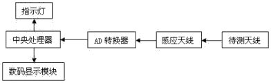
The utility model discloses an intelligent antenna field strength test device which comprises an induction antenna, an antenna to be tested, an AD converter, a central processor, a digital display module and an indicating lamp. The output of the antenna to be tested is connected with the input of the induction antenna. The output of the induction antenna is connected with the input of the AD converter. The output of the AD converter is connected with the central processor. The central processor is connected with the digital display module and the indicating lamp respectively. According to the utility model, the induction antenna is used to receive the strength produced by the field strength of the antenna to be tested, and the test results are visually displayed by a digital display tube and the indicating lamp. The test method is simple and convenient, and the speed of an antenna field strength test is improved. The intelligent antenna field strength test device is suitable for the detection of mass production, and has the characteristics of high precision, low test cost and the like.
Description
Technical field
The utility model relates to a kind of intelligent antenna field intensity proving installation.
Background technology
Along with popularizing of China second-generation identity card in recent years, the arrangement for reading function and the quantity of China second-generation identity card also all are being on the increase, and the quality of the China second-generation identity card equipment especially requirement of Information Security is also being improved constantly; Yet because the function of traditional antenna field strength measurement device is a lot, confidentiality requires also very high; So method more complicated of its test; Measuring accuracy is lower, and the process of test is more loaded down with trivial details, and cost is also than higher; In addition, traditional proving installation also has working environment is required the shortcomings such as detection that height, testing efficiency are low, can not be applicable to batch process.
The utility model content
The purpose of the utility model is to solve the deficiency of existing identity card reader antenna field intensity proving installation; A kind of novel intelligent antenna field intensity proving installation is provided; The method of testing that overcomes the traditional test device is complicated, and cost is higher, and test speed is slow; Efficient is low, can not be applicable to the shortcomings such as detection of batch process.
The purpose of the utility model realizes through following technical scheme: intelligent antenna field intensity proving installation; It comprises induction antenna, antenna to be measured, AD converter, central processing unit, digital display module and pilot lamp; The output of antenna to be measured is connected with the input of induction antenna; The output of induction antenna is connected with the input of AD converter, and the output of AD converter is connected with central processing unit, and central processing unit is connected with pilot lamp with digital display module respectively.
The beneficial effect of the utility model is: utilize induction antenna to receive the field intensity intensity that antenna to be measured sends; Test result is displayed by digital display tube and pilot lamp intuitively; Method of testing is simple and convenient; Improved the speed of antenna field strength measurement,, and had characteristics such as the high and testing cost of degree of accuracy is low applicable to the detection of producing in batches.
Description of drawings
Fig. 1 is the utility model structural representation.
Embodiment
The technical scheme of the utility model is described in further detail: as shown in Figure 1 below in conjunction with accompanying drawing; Intelligent antenna field strength measurement; It comprises induction antenna, antenna to be measured, AD converter, central processing unit, digital display module and pilot lamp, and the output of antenna to be measured is connected with the input of induction antenna, and the output of induction antenna is connected with the input of AD converter; The output of AD converter is connected with central processing unit, and central processing unit is connected with pilot lamp with digital display module respectively.Induction antenna is sensed and is sent to AD converter after the field intensity information of antenna to be measured and carries out the AD conversion; Give CPU through bus transfer after converting digital signal into; CPU is sent to charactron after this digital signal being converted into the control signal of charactron; By the magnitude range of charactron demonstration sample voltage value, indicate this Devices to test whether to meet the requirements through pilot lamp simultaneously.
Claims (1)
1. intelligent antenna field intensity proving installation; It is characterized in that: it comprises induction antenna, antenna to be measured, AD converter, central processing unit, digital display module and pilot lamp; The output of antenna to be measured is connected with the input of induction antenna; The output of induction antenna is connected with the input of AD converter, and the output of AD converter is connected with central processing unit, and central processing unit is connected with pilot lamp with digital display module respectively.
Priority Applications (1)
| Application Number | Priority Date | Filing Date | Title |
|---|---|---|---|
| CN2012201289477U CN202494770U (en) | 2012-03-31 | 2012-03-31 | Intelligent antenna field strength test device |
Applications Claiming Priority (1)
| Application Number | Priority Date | Filing Date | Title |
|---|---|---|---|
| CN2012201289477U CN202494770U (en) | 2012-03-31 | 2012-03-31 | Intelligent antenna field strength test device |
Publications (1)
| Publication Number | Publication Date |
|---|---|
| CN202494770U true CN202494770U (en) | 2012-10-17 |
Family
ID=47000994
Family Applications (1)
| Application Number | Title | Priority Date | Filing Date |
|---|---|---|---|
| CN2012201289477U Expired - Fee Related CN202494770U (en) | 2012-03-31 | 2012-03-31 | Intelligent antenna field strength test device |
Country Status (1)
| Country | Link |
|---|---|
| CN (1) | CN202494770U (en) |
-
2012
- 2012-03-31 CN CN2012201289477U patent/CN202494770U/en not_active Expired - Fee Related
Similar Documents
| Publication | Publication Date | Title |
|---|---|---|
| CN202974544U (en) | Portable digital barometer | |
| CN203798912U (en) | Portable electric field instrument system for site selection | |
| CN103964312B (en) | Electric block energy efficiency testing device and test method | |
| CN202994309U (en) | Multipoint temperature measurement data logging system | |
| CN202522687U (en) | Detection device of frequency converter power supply board | |
| CN202794278U (en) | High-precision handheld type digital oscilloscope | |
| CN202494770U (en) | Intelligent antenna field strength test device | |
| CN203786176U (en) | Intelligent mobile terminal based portable oscilloscope | |
| CN202494745U (en) | Serial type testing device | |
| CN205102775U (en) | Magnetism angle sensor based on MLX90316 | |
| CN203276525U (en) | Embedded test system convenient for near-field data transmission | |
| CN203069744U (en) | Semiconductor triode parameter tester | |
| Ren et al. | Multi-channel temperature measurement system based on LabVIEW | |
| CN203965369U (en) | A kind of construction wall checkout equipment | |
| CN202256238U (en) | Portable edible oil quality detection device | |
| CN201653544U (en) | Laser ageing detection device | |
| CN203349778U (en) | Device for detecting thickness of pouring coverage layer | |
| CN201435072Y (en) | A Universal Data Acquisition Device Based on USB Interface | |
| CN204241602U (en) | A kind of Electronics and Information Engineering testing agency | |
| CN202693759U (en) | High-voltage switch comprehensive tester | |
| CN204694833U (en) | A kind of LED string intelligence energy consumption testing instrument | |
| CN204241515U (en) | A kind of interface adapter detected for hypervelocity magnetoelectricity hard disk | |
| CN204287848U (en) | The digital dynamometry indicator of a kind of analog input | |
| CN205404607U (en) | Many signals anemoscope detection device | |
| CN201926669U (en) | Infrared ray motor rotating speed counter |
Legal Events
| Date | Code | Title | Description |
|---|---|---|---|
| C14 | Grant of patent or utility model | ||
| GR01 | Patent grant | ||
| CF01 | Termination of patent right due to non-payment of annual fee | ||
| CF01 | Termination of patent right due to non-payment of annual fee |
Granted publication date: 20121017 Termination date: 20180331 |