CN202494736U - Device for detecting driving circuit of contactor - Google Patents
Device for detecting driving circuit of contactor Download PDFInfo
- Publication number
- CN202494736U CN202494736U CN2012200495015U CN201220049501U CN202494736U CN 202494736 U CN202494736 U CN 202494736U CN 2012200495015 U CN2012200495015 U CN 2012200495015U CN 201220049501 U CN201220049501 U CN 201220049501U CN 202494736 U CN202494736 U CN 202494736U
- Authority
- CN
- China
- Prior art keywords
- contactor
- driving
- diodes
- driving circuit
- parallel connection
- Prior art date
- Legal status (The legal status is an assumption and is not a legal conclusion. Google has not performed a legal analysis and makes no representation as to the accuracy of the status listed.)
- Expired - Fee Related
Links
- 238000001514 detection method Methods 0.000 claims abstract description 20
- 238000012423 maintenance Methods 0.000 description 2
- 238000005516 engineering process Methods 0.000 description 1
- 238000007689 inspection Methods 0.000 description 1
- 238000005259 measurement Methods 0.000 description 1
- 238000000034 method Methods 0.000 description 1
- 238000007789 sealing Methods 0.000 description 1
Images
Landscapes
- Testing Electric Properties And Detecting Electric Faults (AREA)
Abstract
The utility model discloses a device for detecting a driving circuit of a contactor, and solves the technical problem that failures of the driving circuit of the contactor can not be detected rapidly, economically and conveniently in the prior art. The device comprises a detected contactor (8) and a detection circuit mechanism (7). One end of a load driving power (1) of the detection circuit mechanism (7) is connected with one input end of a driving circuit (6) of the contactor (8), the other input end of the driving circuit (6) of the contactor (8) is connected with one end of two diodes (4) which are in inverse-parallel connection, the other end of the two diodes (4) which are in inverse-parallel connection is connected with the other end of the load driving power (1) of the detection circuit mechanism (7) through a driving switch (2). According to the utility model, rapid detection of driving situations of the driving circuit of the contactor is realized.
Description
Technical field
The utility model relates to a kind of circuit checker, the device that particularly a kind of state of the driving circuit to contactor detects.
Background technology
In power engineering, require important driven electric contactor will guarantee normally to cut-off, this just need detect contactor easily.Prior art is normally passed through the auxiliary contact on driven contactor, and whether detect contactor closed.This detection mode is merely able to judge the duty of contactor itself, can not detect the fault of the driving loop generation of contactor.For fault location point easily, the most directly method is to detect the voltage that drives loop current and driven the contactor two ends, but this mode cost is high, and is dangerous big, and inconvenience is used in actual power engineering.
Summary of the invention
A kind of contactor that the utility model provides drive the loop pick-up unit solved prior art can not be rapidly, economy, detect the technical matters of the driving loop fault of contactor easily.
The utility model solves above technical matters through following technical scheme:
A kind of contactor drives the loop pick-up unit; Comprise contactor to be detected and testing circuit mechanism; An input end of one end of the driving load power source of testing circuit mechanism and the driving circuit of contactor links together; One end of another input end of the driving circuit of contactor and two diodes of reverse parallel connection links together, and the other end of two diodes of reverse parallel connection links together through the other end of the driving load power source of driving switch and testing circuit mechanism.
Two ends at two diodes of reverse parallel connection are provided with the first voltage detection signal end, between two input ends of the driving circuit of contactor, are provided with the second voltage detection signal end, and two diodes of reverse parallel connection are the diode of same model.
The utility model, converts switching value into and measures the loop the analog loopback of original current-voltage measurement through in driving the loop, sealing in antiparallel two diodes, has realized that contactor drives the quick detection of drive circuit situation.
Description of drawings
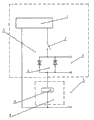
Fig. 1 is the structural representation of the utility model.
Embodiment
A kind of contactor drives the loop pick-up unit; Comprise contactor to be detected 8 and testing circuit mechanism 7; An input end of one end of the driving load power source 1 of testing circuit mechanism 7 and the driving circuit 6 of contactor 8 links together; One end of two diodes 4 of another input end of the driving circuit 6 of contactor 8 and reverse parallel connection links together, and the other end of two diodes 4 of reverse parallel connection links together through the other end of driving switch 2 with the driving load power source 1 of testing circuit mechanism 7.
Two ends at two diodes 4 of reverse parallel connection are provided with the first voltage detection signal end 3, between two input ends of the driving circuit 6 of contactor 8, are provided with the second voltage detection signal end 5, and two diodes of reverse parallel connection are the diode of same model.
Drive antiparallel two the diode D1 of series connection, D2 in the contactor coil loop at driving switch and quilt, and detect the voltage drop at diode two ends.When driving contactor, following situation can appear:
(1) after driving normal and driving switch 2 normally closeds of load power source 1; Driven the contactor normally closed; Then the first voltage detection signal end 3 is the normal tube voltage drop at diode two ends, and the second voltage detection signal end 5 is the load driving supply voltage, contactor auxiliary contact normally closed.
(2) after driving normal and driving switch 2 normally closeds of load power source 1; Driven the contactor fault and failed normally closed; Then the first voltage detection signal end 3 is 0 volt, and the second voltage detection signal end 5 is the load driving supply voltage, and the contactor auxiliary contact are not closed.
(3) after driving normal and normal 2 closures of driving switch of load power source 1; Driver circuit opens circuit and causes contactor to fail normally closed; Then the first voltage detection signal end 3 is 0 volt, and the second voltage detection signal end 5 is the load driving supply voltage, and the contactor auxiliary contact are not closed.
(4) when the load driving power supply undesired or driving switch not normally closed cause contactor to fail normally closed, then the first voltage detection signal end 3 is 0 volt, the second voltage detection signal end 5 is 0 pair, the contactor auxiliary contact are not closed.
In above four kinds of situation, situation (1) is system's nominal situation, without any need for maintenance.Situation (2) is the contactor fault, can notify the maintenance personal that contactor is changed.Situation (3) opens circuit for driver circuit or contactor coil opens circuit, and can notify the maintainer to driver circuit, contactor coil and inspection of each connection terminal and replacing.Situation (4) is the internal drive fault, can notify the maintainer more to renew driver.
Claims (2)
1. a contactor drives the loop pick-up unit; Comprise contactor to be detected (8) and testing circuit mechanism (7); It is characterized in that; An input end of one end of the driving load power source (1) of testing circuit mechanism (7) and the driving circuit (6) of contactor (8) links together; One end of another input end of the driving circuit (6) of contactor (8) and two diodes (4) of reverse parallel connection links together, and the other end of two diodes (4) of reverse parallel connection links together through the other end of driving switch (2) with the driving load power source (1) of testing circuit mechanism (7).
2. a kind of contactor according to claim 1 drives the loop pick-up unit; It is characterized in that; Two ends at two diodes (4) of reverse parallel connection are provided with the first voltage detection signal end (3); Between two input ends of the driving circuit (6) of contactor (8), be provided with the second voltage detection signal end (5), two diodes of reverse parallel connection are the diode of same model.
Priority Applications (1)
| Application Number | Priority Date | Filing Date | Title |
|---|---|---|---|
| CN2012200495015U CN202494736U (en) | 2012-02-16 | 2012-02-16 | Device for detecting driving circuit of contactor |
Applications Claiming Priority (1)
| Application Number | Priority Date | Filing Date | Title |
|---|---|---|---|
| CN2012200495015U CN202494736U (en) | 2012-02-16 | 2012-02-16 | Device for detecting driving circuit of contactor |
Publications (1)
| Publication Number | Publication Date |
|---|---|
| CN202494736U true CN202494736U (en) | 2012-10-17 |
Family
ID=47000961
Family Applications (1)
| Application Number | Title | Priority Date | Filing Date |
|---|---|---|---|
| CN2012200495015U Expired - Fee Related CN202494736U (en) | 2012-02-16 | 2012-02-16 | Device for detecting driving circuit of contactor |
Country Status (1)
| Country | Link |
|---|---|
| CN (1) | CN202494736U (en) |
-
2012
- 2012-02-16 CN CN2012200495015U patent/CN202494736U/en not_active Expired - Fee Related
Similar Documents
| Publication | Publication Date | Title |
|---|---|---|
| CN101571572B (en) | Detection device and detection method for state of relay contact in automotive high voltage circuit | |
| CN202837494U (en) | Contactor state inspection device | |
| CN104228588B (en) | High-voltage loop diagnostic circuit of pure electric vehicle | |
| CN201438207U (en) | Relay fault detection circuit | |
| CN102385036B (en) | Method and circuit for detecting alternating-current fuse failure of uninterruptible power supply | |
| CN104730441B (en) | Transistors breakdown detection device | |
| CN203198756U (en) | Monitoring and alarm device for electric car high-tension distribution system | |
| CN204575756U (en) | Capacitor faults indicating circuit, multiple capacitor faults indicator circuit and system | |
| CN105429548A (en) | Electric Motor Drive Apparatus Having Function For Detecting Welding Of Electromagnetic Contactor | |
| CN103399571A (en) | Detecting device and method applied to high-voltage circuit of electromobile motor controller | |
| CN105676048A (en) | Transformer station switch cabinet switch secondary circuit detection device | |
| CN203368336U (en) | Frequency converter | |
| CN102761097A (en) | Direct current leakage protective circuit | |
| CN102565662A (en) | State detection device for high-potential thyristor | |
| CN204895155U (en) | Circuit, electric automobile control system and electric automobile on electric automobile high pressure | |
| CN101368999A (en) | A portable anti-parallel thyristor zero-crossing trigger detection device | |
| CN102969693A (en) | Electronic control valve driving protective circuit of railway vehicles | |
| CN202494736U (en) | Device for detecting driving circuit of contactor | |
| CN205861871U (en) | A kind of fault detection system for high frequency switch power | |
| CN204696641U (en) | A kind of equipment for the protection of high-tension battery using electricity system and the vehicle with this equipment | |
| CN203465391U (en) | High-voltage thyristor fault detection device without optical fiber isolation | |
| CN101699305B (en) | Automatic circuit fault diagnosis and alarm device | |
| CN201255763Y (en) | Electric bicycle failure automatic detection and display apparatus and electric bicycle | |
| US20190084424A1 (en) | Contactor supply bus | |
| CN204832407U (en) | A high -voltage circuit detection device for electric motor car |
Legal Events
| Date | Code | Title | Description |
|---|---|---|---|
| C14 | Grant of patent or utility model | ||
| GR01 | Patent grant | ||
| CF01 | Termination of patent right due to non-payment of annual fee |
Granted publication date: 20121017 Termination date: 20150216 |
|
| EXPY | Termination of patent right or utility model |