CN202494558U - Pneumatic conveying ultrasonic on-line test system - Google Patents
Pneumatic conveying ultrasonic on-line test system Download PDFInfo
- Publication number
- CN202494558U CN202494558U CN201220075810XU CN201220075810U CN202494558U CN 202494558 U CN202494558 U CN 202494558U CN 201220075810X U CN201220075810X U CN 201220075810XU CN 201220075810 U CN201220075810 U CN 201220075810U CN 202494558 U CN202494558 U CN 202494558U
- Authority
- CN
- China
- Prior art keywords
- ultrasonic
- weighing instrument
- electronic weighing
- jar
- material receiving
- Prior art date
- Legal status (The legal status is an assumption and is not a legal conclusion. Google has not performed a legal analysis and makes no representation as to the accuracy of the status listed.)
- Expired - Fee Related
Links
- 238000012360 testing method Methods 0.000 title claims abstract description 18
- 239000000463 material Substances 0.000 claims abstract description 18
- 239000000523 sample Substances 0.000 claims abstract description 13
- 238000005303 weighing Methods 0.000 claims abstract description 12
- 239000007787 solid Substances 0.000 abstract description 10
- 239000000843 powder Substances 0.000 abstract description 3
- 238000005516 engineering process Methods 0.000 description 14
- 238000011161 development Methods 0.000 description 3
- 238000005259 measurement Methods 0.000 description 3
- 230000005514 two-phase flow Effects 0.000 description 3
- 238000010586 diagram Methods 0.000 description 2
- 238000009826 distribution Methods 0.000 description 2
- 239000012530 fluid Substances 0.000 description 2
- 238000000034 method Methods 0.000 description 2
- 238000011160 research Methods 0.000 description 2
- 238000002604 ultrasonography Methods 0.000 description 2
- 238000012271 agricultural production Methods 0.000 description 1
- 238000004364 calculation method Methods 0.000 description 1
- 238000004587 chromatography analysis Methods 0.000 description 1
- 238000010276 construction Methods 0.000 description 1
- 230000000694 effects Effects 0.000 description 1
- 238000005265 energy consumption Methods 0.000 description 1
- 238000002474 experimental method Methods 0.000 description 1
- 238000003384 imaging method Methods 0.000 description 1
- 238000009776 industrial production Methods 0.000 description 1
- 238000009434 installation Methods 0.000 description 1
- 238000000691 measurement method Methods 0.000 description 1
- 239000002245 particle Substances 0.000 description 1
- 238000012545 processing Methods 0.000 description 1
- 230000000644 propagated effect Effects 0.000 description 1
- 238000012797 qualification Methods 0.000 description 1
- 238000000926 separation method Methods 0.000 description 1
- 239000000126 substance Substances 0.000 description 1
- 239000000725 suspension Substances 0.000 description 1
- 238000012546 transfer Methods 0.000 description 1
Images
Landscapes
- Investigating Or Analyzing Materials By The Use Of Ultrasonic Waves (AREA)
Abstract
The utility model discloses a pneumatic conveying ultrasonic on-line test system which comprises a gas source apparatus. The pneumatic conveying ultrasonic on-line test system is characterized in that: the gas source apparatus is connected to a material feeding can through a vortex flowmeter, the material feeding can is connected with a material receiving can through a main pipeline, an electronic weighing instrument is provided on the material receiving can, the main pipeline is connected to an ultrasonic test device and a pressure sensor, and the vortex flowmeter, an ultrasonic probe, the pressure sensor, and the electronic weighing instrument are all connected to a computer. According to the utility model, gas-solid two phases are sent out by the material feeding can and enter the material receiving can through the main pipeline, and the vortex flowmeter is used to test and record the gas flow; powder mass received by the material receiving can is read and determined through the electronic weighing instrument installed on the material receiving can; and the ultrasonic test device and the pressure sensor are installed at corresponding positions on the stable flow section of the main pipeline to collect and analyze flow field information.
Description
Technical field
The utility model relates to a kind of strength and carries the Ultrasonic On-line test macro.
Background technology
Dual-Phrase Distribution of Gas olid technology (being called strength again carries) is to utilize the technology of air-flow as carrier conveying solid substance material in pipeline.At present, Pneumatic Conveying Technology has been widely used in the every field of industrial and agricultural production because advantages such as device safety, robotization height, clean environment firendly, easy to operate, flexible arrangement, becomes one of important means indispensable in the Modern Logistics Technology.
The general mode of movement of middle and high concentration (the solid and gas mass ratio is greater than 20) of claiming is carried for the concentrated phase strength.Compare with traditional dilute suspension mode of movement, the concentrated phase conveying is low owing to transporting velocity, solid-gas ratio big, the little particle that makes of gas solid separation amount is lighter to pipe wear, has the low and high characteristics of transfer efficiency of energy consumption.But also also immature at present aspect the research of theoretical and application, bigger to the dependence of experiment.So being carried out deep research, the middle and high concentration Gas-solid Two-phase Flow has important application.
For a long time, Dual-Phrase Distribution of Gas olid especially the flow-field test problem of high concentration diphasic flow be always the restriction its development bottleneck.Though this technology had obtained large development in recent years; High-end measuring technologies such as capacitance chromatography imaging method, Doppler technology, X ray technology, laser measurement, PIV technology, rest potential measurement have successively appearred; But these technology are mostly only for being used among the less dilute phase of solid concentration flows, and these measuring technologies flowing environment is required too high, relatively poor to the pipeline applicability of relative complex; Instrument costs an arm and a leg, and expense is too high.Therefore, the method for testing of exploring cheap novel test means or using for reference other applications is to solve the effective way that Gas-solid Two-phase Flow is measured difficulty at present.
The ultrasonic tesint technology is one of flow field measurement technique commonly used.When ultrasound wave is propagated, can carry information about fluids in fluid.Therefore, the ultrasonic signal that receives is carried out analytical calculation, can detect relevant flow field information.The ultrasonic tesint technical development is very fast, it have measurement range wide, measure accurately, receive medium parameter to influence advantage such as little, easy for installation and widespread use.To Gas-solid Two-phase Flow field ultrasonic tesint Study on Technology and exploitation, have important use and be worth.
The utility model content
The technical matters that the utility model will solve provides a kind of strength and carries the Ultrasonic On-line test macro.
The utility model adopts following technological means to realize goal of the invention:
A kind of strength is carried the Ultrasonic On-line test macro; Comprise compressed air source unit; It is characterized in that: said compressed air source unit connects the issuance of materials jar through vortex shedding flow meter, and said issuance of materials jar connects the rewinding jar through main line, and said rewinding jar is provided with electronic weighing instrument; Said main line connects ultrasonic tesint equipment and pressure transducer, and said vortex shedding flow meter, ultrasonic probe, pressure transducer and electronic weighing instrument all are connected to computing machine.
As further qualification to the present technique scheme; Said ultrasonic tesint equipment comprises ultrasonic generator, ultrasonic receiver and ultrasonic probe; Said ultrasonic generator is connected ultrasonic probe with the equal via line of ultrasonic receiver; Said ultrasonic probe is installed on main line, and said ultrasonic generator and ultrasonic receiver all are connected in computing machine.
Compared with prior art, the advantage of the utility model with good effect is: the utility model gas-solid two is seen off by the issuance of materials jar, gets into the rewinding jar through main line, adopts vortex shedding flow meter that gas flow is tested and record; Confirm the powder quality that the rewinding jar is accepted through the electronic weighing instrument reading that is installed on the rewinding jar; The mobile stable section corresponding site of main line is installed ultrasonic tesint equipment and pressure transducer, and stream field information is gathered and analyzed.
Description of drawings
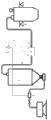
Fig. 1 is the utility model one-piece construction synoptic diagram.
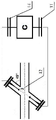
Fig. 2 is a ultrasonic tesint device structure synoptic diagram.
Embodiment
Below in conjunction with accompanying drawing and preferred embodiment the utility model is made detailed description further.
Referring to Fig. 1, Fig. 2, the utility model structure comprises compressed air source unit 1, vortex shedding flow meter 2, issuance of materials jar 3, main line 4, rewinding jar 5, ultrasonic tesint equipment 6, pressure transducer 7, electronic weighing instrument 8, computing machine 9, ultrasonic generator 10, ultrasonic receiver 11, ultrasonic probe 12.Said compressed air source unit 1 connects issuance of materials jar 3 through vortex shedding flow meter 2; Said issuance of materials jar 3 connects main line 4; Said main line 4 connects rewinding jar 5; Said rewinding jar 5 is provided with electronic weighing instrument 8, and said main line 4 connects ultrasonic tesint equipment 6 and pressure transducers 7, and said vortex shedding flow meter 2, ultrasonic tesint equipment 6, pressure transducer 7 and electronic weighing instrument 8 all are connected to computing machine 9.The utility model gas-solid two is seen off by issuance of materials jar 3, gets into rewinding jar 5 through main line 4.Adopt 2 pairs of gas flows of vortex shedding flow meter to test and record; Confirm the powder quality that the rewinding jar is accepted through electronic weighing instrument 8 readings that are installed on rewinding jar 5; Main line 4 mobile stable sections are installed ultrasonic probe 6; The stream field information signal is gathered and is analyzed; Said ultrasonic generator 10 is connected ultrasonic probe 6 with ultrasonic receiver 11 equal via line, and said ultrasonic generator 10 all is connected in computing machine 9 with ultrasonic receiver 11.During test, ultrasound wave is sent by ultrasonic generator 10, tests through excusing from death probe 6, is received signal message and is carried out signal Processing by computing machine 9 by ultrasonic receiver 11.Pressure variation on 7 pairs of main lines 4 of pressure transducer is simultaneously monitored in real time.
Claims (2)
1. a strength is carried the Ultrasonic On-line test macro; Comprise compressed air source unit; It is characterized in that: said compressed air source unit connects the issuance of materials jar through vortex shedding flow meter, and said issuance of materials jar connects the rewinding jar through main line, and said rewinding jar is provided with electronic weighing instrument; Said main line connects ultrasonic tesint equipment and pressure transducer, and said vortex shedding flow meter, ultrasonic probe, pressure transducer and electronic weighing instrument all are connected to computing machine.
2. carry the Ultrasonic On-line test macro according to the said strength of claim 1; It is characterized in that: said ultrasonic tesint equipment comprises ultrasonic generator, ultrasonic receiver and ultrasonic probe; Said ultrasonic generator is connected ultrasonic probe with the equal via line of ultrasonic receiver; Said ultrasonic probe is installed on main line, and said ultrasonic generator and ultrasonic receiver all are connected in computing machine.
Priority Applications (1)
| Application Number | Priority Date | Filing Date | Title |
|---|---|---|---|
| CN201220075810XU CN202494558U (en) | 2012-03-02 | 2012-03-02 | Pneumatic conveying ultrasonic on-line test system |
Applications Claiming Priority (1)
| Application Number | Priority Date | Filing Date | Title |
|---|---|---|---|
| CN201220075810XU CN202494558U (en) | 2012-03-02 | 2012-03-02 | Pneumatic conveying ultrasonic on-line test system |
Publications (1)
| Publication Number | Publication Date |
|---|---|
| CN202494558U true CN202494558U (en) | 2012-10-17 |
Family
ID=47000783
Family Applications (1)
| Application Number | Title | Priority Date | Filing Date |
|---|---|---|---|
| CN201220075810XU Expired - Fee Related CN202494558U (en) | 2012-03-02 | 2012-03-02 | Pneumatic conveying ultrasonic on-line test system |
Country Status (1)
| Country | Link |
|---|---|
| CN (1) | CN202494558U (en) |
-
2012
- 2012-03-02 CN CN201220075810XU patent/CN202494558U/en not_active Expired - Fee Related
Similar Documents
| Publication | Publication Date | Title |
|---|---|---|
| CN102435237A (en) | Gas-solid two-phase flow parameter detector | |
| CN111351540B (en) | Method and system for detecting mass flow rate of particles in pneumatic conveying process | |
| CN101173865A (en) | Device and method for measuring parameters of gas-solid two-phase flow in square pneumatic conveying pipeline | |
| Sun et al. | Mass flow measurement of pneumatically conveyed solids using electrical capacitance tomography | |
| CN101788313B (en) | High Response Fluid Transient Flowmeter | |
| CN101162165A (en) | Low gas content gas-liquid two-phase flow measuring apparatus based on capacitance sensor and standard venturi tube | |
| Coombes et al. | Measurement of velocity and concentration profiles of pneumatically conveyed particles using an electrostatic sensor array | |
| Sun et al. | Investigation of the pressure probe properties as the sensor in the vortex flowmeter | |
| CN109932419A (en) | Corrosion detection device and method in crude oil pipeline | |
| CN107367305A (en) | A kind of moment of torsion flowmeter and its method of work | |
| CN202255473U (en) | Intelligent quake-proof vortex precession flow meter | |
| CN102080976A (en) | Wide-range gas flow detector | |
| CN202494558U (en) | Pneumatic conveying ultrasonic on-line test system | |
| CN202492151U (en) | Pneumatic conveying branch pipeline flow testing device | |
| CN202057360U (en) | Combined gas flow meter | |
| CN202562533U (en) | A gas flow measuring device metering from zero | |
| CN206470284U (en) | The measurement apparatus of gas in pipelines flow velocity | |
| Zhou et al. | Relationship between pneumatic conveying flow regimes and acoustic signals based on DWT and HHT analysis | |
| Wang et al. | Local particle mean velocity measurement in pneumatic conveying pipelines using electrostatic sensor arrays | |
| CN206788610U (en) | A kind of measurement apparatus | |
| CA2868978A1 (en) | Speed of sound and/or density measurement using acoustic impedance | |
| Guo et al. | Application of a microwave mass flow meter in a dense phase pneumatic conveying system of pulverized coal | |
| CN201297973Y (en) | Non-contact on-line integrated monitoring system of a bubble or slurry bed | |
| Sen et al. | PC-based gas-solids two-phase mass flowmeter for pneumatically conveying systems | |
| CN206095327U (en) | Compound multichannel flowmeter and flow metering device thereof |
Legal Events
| Date | Code | Title | Description |
|---|---|---|---|
| C14 | Grant of patent or utility model | ||
| GR01 | Patent grant | ||
| C17 | Cessation of patent right | ||
| CF01 | Termination of patent right due to non-payment of annual fee |
Granted publication date: 20121017 Termination date: 20130302 |