CN202494544U - Isolation tank - Google Patents
Isolation tank Download PDFInfo
- Publication number
- CN202494544U CN202494544U CN2012201185389U CN201220118538U CN202494544U CN 202494544 U CN202494544 U CN 202494544U CN 2012201185389 U CN2012201185389 U CN 2012201185389U CN 201220118538 U CN201220118538 U CN 201220118538U CN 202494544 U CN202494544 U CN 202494544U
- Authority
- CN
- China
- Prior art keywords
- cavity
- tank body
- pipeline
- isolation
- tank
- Prior art date
- Legal status (The legal status is an assumption and is not a legal conclusion. Google has not performed a legal analysis and makes no representation as to the accuracy of the status listed.)
- Expired - Fee Related
Links
- 238000002955 isolation Methods 0.000 title abstract description 25
- 239000010865 sewage Substances 0.000 claims abstract description 8
- 238000012423 maintenance Methods 0.000 claims abstract description 7
- 229910001220 stainless steel Inorganic materials 0.000 claims description 3
- 239000010935 stainless steel Substances 0.000 claims description 3
- 238000007789 sealing Methods 0.000 claims 2
- 238000009434 installation Methods 0.000 abstract description 4
- 238000000926 separation method Methods 0.000 abstract 1
- 239000007788 liquid Substances 0.000 description 19
- 238000000034 method Methods 0.000 description 6
- 230000005540 biological transmission Effects 0.000 description 4
- 125000006850 spacer group Chemical group 0.000 description 4
- 239000012530 fluid Substances 0.000 description 3
- 230000003139 buffering effect Effects 0.000 description 2
- 238000013461 design Methods 0.000 description 2
- 238000004945 emulsification Methods 0.000 description 2
- 238000005259 measurement Methods 0.000 description 2
- 239000003921 oil Substances 0.000 description 2
- 230000009286 beneficial effect Effects 0.000 description 1
- 230000001010 compromised effect Effects 0.000 description 1
- 238000009833 condensation Methods 0.000 description 1
- 230000005494 condensation Effects 0.000 description 1
- 239000010779 crude oil Substances 0.000 description 1
- 230000006866 deterioration Effects 0.000 description 1
- 238000006073 displacement reaction Methods 0.000 description 1
- 238000005516 engineering process Methods 0.000 description 1
- 230000008014 freezing Effects 0.000 description 1
- 238000007710 freezing Methods 0.000 description 1
- 238000007689 inspection Methods 0.000 description 1
- 238000010079 rubber tapping Methods 0.000 description 1
- 239000000126 substance Substances 0.000 description 1
- 238000012360 testing method Methods 0.000 description 1
- 230000009466 transformation Effects 0.000 description 1
- 238000000844 transformation Methods 0.000 description 1
- 238000009834 vaporization Methods 0.000 description 1
- 230000008016 vaporization Effects 0.000 description 1
Images

Classifications
-
- Y—GENERAL TAGGING OF NEW TECHNOLOGICAL DEVELOPMENTS; GENERAL TAGGING OF CROSS-SECTIONAL TECHNOLOGIES SPANNING OVER SEVERAL SECTIONS OF THE IPC; TECHNICAL SUBJECTS COVERED BY FORMER USPC CROSS-REFERENCE ART COLLECTIONS [XRACs] AND DIGESTS
- Y02—TECHNOLOGIES OR APPLICATIONS FOR MITIGATION OR ADAPTATION AGAINST CLIMATE CHANGE
- Y02A—TECHNOLOGIES FOR ADAPTATION TO CLIMATE CHANGE
- Y02A20/00—Water conservation; Efficient water supply; Efficient water use
Landscapes
- Measuring Fluid Pressure (AREA)
Abstract
一种隔离罐,包括罐体,所述罐体中部设置有一隔离板,所述隔离板将罐体分隔成底部相连通的第一腔体和第二腔体,所述第一腔体对应的罐体上设置有管道接口和第一检修排污口,所述第二腔体对应的罐体上设置有压力仪表安装接口和第二检修排污口,管道经管道接口进入第一腔体,所述进入第一腔体内的管道为U形弯管。本实用新型结构简单,能够防止管道中的油品直接与压力仪表接触,适合推广应用。
An isolation tank, comprising a tank body, a separation plate is arranged in the middle of the tank body, and the isolation plate divides the tank body into a first cavity and a second cavity connected at the bottom, and the first cavity corresponds to The tank body is provided with a pipeline interface and a first maintenance sewage outlet, and the tank body corresponding to the second cavity is provided with a pressure instrument installation interface and a second maintenance sewage outlet. The pipeline enters the first cavity through the pipeline interface, and the The pipeline entering the first cavity is a U-shaped elbow. The utility model has a simple structure, can prevent the oil product in the pipeline from directly contacting the pressure instrument, and is suitable for popularization and application.
Description
技术领域 technical field
本实用新型涉及一种测量输送原油管道中管道的压力的中间传导装置,特别是一种隔离罐。The utility model relates to an intermediate transmission device for measuring the pressure of a pipeline in a crude oil pipeline, in particular to an isolation tank.
背景技术 Background technique
隔离是仪表测量中防止被测物质进入仪表或仪表引线的常用方法,也是防止由于存在冷凝(产生附加液柱)、汽化、粘稠液体、腐蚀性介质或沉积物以及冻结而致使仪表操作不良,甚至受到损害的常用方法。Isolation is a common method in meter measurement to prevent the measured substance from entering the meter or meter leads, and it is also to prevent poor meter operation due to the presence of condensation (generating additional liquid columns), vaporization, viscous liquids, corrosive media or deposits, and freezing. Common methods that are even compromised.
目前常用的隔离罐往往从罐体侧部取压,不容易使隔离液真正装满整个罐体,即使装满了,一旦打开取压阀,罐中隔离液液面也会下降。因此,在取压过程中,往往使工艺介质进入隔离罐内,造成工艺介质与隔离液强或较强接触,从产生置换、混溶现象,使隔离液在短时间内,甚至两三天内就变质失效,起不到隔离液作用,使测量不准确、不稳定。随之还带来易堵、易冻、易腐蚀等弊端,甚至造成事故或事故隐患。Currently commonly used isolating tanks often take pressure from the side of the tank, and it is not easy to fill the entire tank with the insulating liquid. Even if it is full, once the pressure tapping valve is opened, the liquid level of the isolating liquid in the tank will drop. Therefore, in the process of pressure taking, the process medium often enters the isolation tank, resulting in strong or strong contact between the process medium and the spacer liquid, resulting in displacement and miscibility, and the spacer liquid disappears within a short period of time, even within two or three days. Deterioration fails, and it cannot play the role of spacer, making the measurement inaccurate and unstable. It also brings disadvantages such as easy to block, easy to freeze, and easy to corrode, and even cause accidents or hidden dangers.
实用新型内容 Utility model content
为克服上述同类技术存在的不足,本实用新型的目的是提供一种能够防止管道中的油品直接与压力仪表接触的隔离罐。In order to overcome the shortcomings of the above similar technologies, the purpose of this utility model is to provide an isolation tank that can prevent the oil in the pipeline from directly contacting the pressure instrument.
本实用新型的技术方案是:一种隔离罐,包括罐体,所述罐体中部设置有一隔离板,所述隔离板将罐体分隔成底部相连通的第一腔体和第二腔体,所述第一腔体对应的罐体上设置有管道接口和第一检修排污口,所述第二腔体对应的罐体上设置有压力仪表安装接口和第二检修排污口,管道经管道接口进入第一腔体,所述进入第一腔体内的管道为U形弯管。The technical solution of the present utility model is: an isolation tank, comprising a tank body, an isolation plate is arranged in the middle of the tank body, and the isolation plate separates the tank body into a first cavity and a second cavity connected at the bottom, The tank body corresponding to the first cavity is provided with a pipeline interface and a first maintenance sewage outlet, the tank body corresponding to the second cavity is provided with a pressure instrument installation interface and a second maintenance sewage outlet, and the pipeline passes through the pipeline interface Entering the first cavity, the pipeline entering the first cavity is a U-shaped elbow.
作为优选技术方案,本实用新型所述罐体为圆柱形不锈钢罐体。As a preferred technical solution, the tank body described in the utility model is a cylindrical stainless steel tank body.
本实用新型的有益效果是:The beneficial effects of the utility model are:
本实用新型可以很好的减缓隔离罐罐体内液体的乳化速度,在管道中的液体波动剧烈时,U形弯管可以起到很好的缓冲作用。另外隔离板的设计可以延长隔离罐的充装次数,当第一腔体内管道中的液体乳化后,液体会通过隔离板底部流到第二腔体中,这样可以始终保持压力传导管中的液体为隔离液,防止管道中的油品直接与压力仪表接触。The utility model can well slow down the emulsification speed of the liquid in the isolation tank, and when the liquid in the pipeline fluctuates violently, the U-shaped elbow can play a good buffering role. In addition, the design of the isolation plate can prolong the filling times of the isolation tank. When the liquid in the pipeline in the first cavity is emulsified, the liquid will flow into the second cavity through the bottom of the isolation plate, so that the liquid in the pressure transmission tube can always be maintained. As an isolation fluid, prevent the oil in the pipeline from directly contacting the pressure gauge.
附图说明 Description of drawings
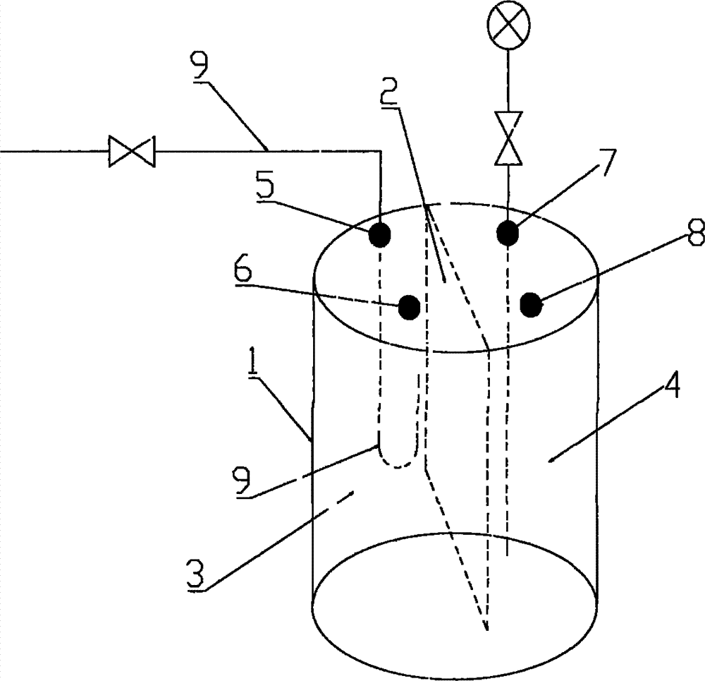
图1是本实用新型的结构示意图。Fig. 1 is the structural representation of the utility model.
具体实施方式 Detailed ways
下面结合具体实施例,进一步阐述本实用新型。Below in conjunction with specific embodiment, further set forth the utility model.
参照图1,提出本实用新型的一具体实施例,一种隔离罐,包括罐体1,所述罐体1中部设置有一隔离板2,所述隔离板2将罐体1分隔成底部相连通的第一腔体3和第二腔体4,所述第一腔体3对应的罐体1上设置有管道接口5和第一检修排污口6,所述第二腔体4对应的罐体1上设置有压力仪表安装接口7和第二检修排污口8,管道9经管道接口5进入第一腔体3,所述进入第一腔体3内的管道9为U形弯管,所述压力仪表安装接口7用来安装压力显示仪表指示及充装隔离液的压力传导管。本实用新型可以很好的减缓隔离罐罐体内液体的乳化速度,在管道中的液体波动剧烈时,U形弯管可以起到很好的缓冲作用。另外隔离板的设计可以延长隔离罐的充装次数,当第一腔体内管道中的液体乳化后,液体会通过隔离板底部流到第二腔体中,这样可以始终保持压力传导管中的液体为隔离液。With reference to Fig. 1, a specific embodiment of the present utility model is proposed, a kind of isolation tank, comprises tank body 1, and the middle part of described tank body 1 is provided with an isolation plate 2, and described isolation plate 2 separates tank body 1 into the bottom and communicates with each other. The
所述罐体1为圆柱形不锈钢罐体。经过试验打压可以承受10MPa的压力。本实用新型提供的隔离罐适合管道中的液体密度小于隔离液的密度的情形使用。The tank 1 is a cylindrical stainless steel tank. After testing, it can withstand the pressure of 10MPa. The isolation tank provided by the utility model is suitable for the situation that the density of the liquid in the pipeline is lower than that of the isolation liquid.
以上所述仅为本实用新型的优选实施例,并非因此而限制本实用新型的专利范围,凡是利用本实用新型说明书及附图内容所作的等效结构变换,或直接或间接运用在其他相关的技术领域,均同理包括在本实用新型的专利保护范围内。The above descriptions are only preferred embodiments of the present utility model, and are not intended to limit the patent scope of the present utility model. All equivalent structural transformations made by using the description of the utility model and the contents of the accompanying drawings, or directly or indirectly used in other related Technical fields are all included in the scope of patent protection of the utility model in the same way.
Claims (2)
Priority Applications (1)
| Application Number | Priority Date | Filing Date | Title |
|---|---|---|---|
| CN2012201185389U CN202494544U (en) | 2012-03-18 | 2012-03-18 | Isolation tank |
Applications Claiming Priority (1)
| Application Number | Priority Date | Filing Date | Title |
|---|---|---|---|
| CN2012201185389U CN202494544U (en) | 2012-03-18 | 2012-03-18 | Isolation tank |
Publications (1)
| Publication Number | Publication Date |
|---|---|
| CN202494544U true CN202494544U (en) | 2012-10-17 |
Family
ID=47000769
Family Applications (1)
| Application Number | Title | Priority Date | Filing Date |
|---|---|---|---|
| CN2012201185389U Expired - Fee Related CN202494544U (en) | 2012-03-18 | 2012-03-18 | Isolation tank |
Country Status (1)
| Country | Link |
|---|---|
| CN (1) | CN202494544U (en) |
-
2012
- 2012-03-18 CN CN2012201185389U patent/CN202494544U/en not_active Expired - Fee Related
Similar Documents
| Publication | Publication Date | Title |
|---|---|---|
| CN204461965U (en) | Adding pressure type rock permeability instrument | |
| CN201818297U (en) | Oil-gas-water three phase automatic metering device | |
| CN103344525B (en) | Method and device for testing effective viscosity of foams in pore medium | |
| CN210268841U (en) | Heavy oil magnetic turning plate liquid level meter | |
| CN201378135Y (en) | Liquid and on-line fluid density measuring device | |
| CN208155801U (en) | A kind of spontaneous imbibition visualization pressurization measuring device of rock core | |
| CN106441698B (en) | The unstable pressure difference meter of high pressure and its use and check method | |
| CN202494544U (en) | Isolation tank | |
| CN206192571U (en) | Type of falling U pipe differential gauge | |
| CN210802601U (en) | Measuring system for dynamic liquid level in pipe under steam water working condition | |
| CN205003131U (en) | Integration hydrogen concentration monitoring devices | |
| CN201045585Y (en) | Pressure container glass tube liquid level meter | |
| CN106338357A (en) | Inverted-U-shaped-tube differential pressure gauge | |
| CN203024920U (en) | High-pressure sulphur-tolerant pressure gauge with straight-through type C-shaped spring tube | |
| CN204027640U (en) | Oil well associated gas measuring device for gas | |
| CN110439488B (en) | System and method for measuring flow of solid-liquid fluid in drilling manifold | |
| CN204223558U (en) | Wine tank liquidometer | |
| CN204543927U (en) | Desulfuration absorbing tower liquid-level pressure transmitter back purge system | |
| CN204064402U (en) | Diesel oil hydrogenation corrosion inhibiter tank fluid level gauge | |
| CN2932322Y (en) | Fluid measuring device for petroleum reservoir physic test | |
| CN106352940A (en) | An anti-clogging device for lower liquid level | |
| CN206300751U (en) | A kind of manometric anti-condensation sealing chamber | |
| CN206223347U (en) | The unstable pressure difference meter of high pressure | |
| EA201100991A1 (en) | METHOD OF MEASURING OIL WELL DEBIT AND THE DEVICE FOR ITS IMPLEMENTATION | |
| CN118583236B (en) | Double differential pressure type two-phase flow metering device |
Legal Events
| Date | Code | Title | Description |
|---|---|---|---|
| C14 | Grant of patent or utility model | ||
| GR01 | Patent grant | ||
| DD01 | Delivery of document by public notice |
Addressee: Zhang Chao Document name: Notification of Termination of Patent Right |
|
| C17 | Cessation of patent right | ||
| CF01 | Termination of patent right due to non-payment of annual fee |
Granted publication date: 20121017 Termination date: 20140318 |