CN202494436U - Centering device - Google Patents
Centering device Download PDFInfo
- Publication number
- CN202494436U CN202494436U CN2012200026563U CN201220002656U CN202494436U CN 202494436 U CN202494436 U CN 202494436U CN 2012200026563 U CN2012200026563 U CN 2012200026563U CN 201220002656 U CN201220002656 U CN 201220002656U CN 202494436 U CN202494436 U CN 202494436U
- Authority
- CN
- China
- Prior art keywords
- rotating shaft
- centering
- air
- centering platform
- platform
- Prior art date
- Legal status (The legal status is an assumption and is not a legal conclusion. Google has not performed a legal analysis and makes no representation as to the accuracy of the status listed.)
- Expired - Lifetime
Links
- 230000005855 radiation Effects 0.000 claims 1
- 238000000034 method Methods 0.000 description 7
- 238000002347 injection Methods 0.000 description 5
- 239000007924 injection Substances 0.000 description 5
- 238000010586 diagram Methods 0.000 description 3
- 238000006243 chemical reaction Methods 0.000 description 2
- 238000000354 decomposition reaction Methods 0.000 description 2
- 238000001514 detection method Methods 0.000 description 1
- 238000005259 measurement Methods 0.000 description 1
- 238000005096 rolling process Methods 0.000 description 1
- 238000000926 separation method Methods 0.000 description 1
Images


Landscapes
- Magnetic Bearings And Hydrostatic Bearings (AREA)
Abstract
本实用新型公开了定心装置,包括用于放置零件的定心平台,定心平台具有使用时与水平面平齐的放置平面,定心平台上设置有转动轴线与放置平面垂直的喷气式旋翼,所述的喷气式旋翼包括转轴,转轴上设置有沿转轴径向延伸的支撑体,转轴及支撑体内部设置有相互连通的气道,所述的支撑体的悬伸端设置有与气道相连通的喷气口,所述喷气口与气道连通的喷气道与喷气口过中心的直线具有一个夹角,本实用新型只需将零件放置到定心平台上,通过喷气式旋翼产生稳定的气流场实现自动定心,无需人工操作,减少了人工误差,使零件定心更精确,并且零件整体受力小,不易产生变形,减少了废品率。
The utility model discloses a centering device, which includes a centering platform for placing parts. The centering platform has a placement plane that is flush with the horizontal plane when in use. The centering platform is provided with a jet rotor whose rotation axis is perpendicular to the placement plane. The jet-type rotor includes a rotating shaft, on which a supporting body extending radially along the rotating shaft is arranged, and an air channel communicating with each other is arranged inside the rotating shaft and the supporting body, and the overhanging end of the supporting body is provided with a There is an included angle between the air outlet connected to the air passage and the straight line passing through the center of the air outlet. The utility model only needs to place the parts on the centering platform to generate a stable air flow through the jet rotor. The field realizes automatic centering without manual operation, reduces manual errors, makes the centering of parts more accurate, and the overall force of the parts is small, it is not easy to deform, and the scrap rate is reduced.
Description
技术领域 technical field
本实用新型涉及定心装置,尤其涉及环形体或套管等的中空回转体的定心装置。 The utility model relates to a centering device, in particular to a centering device for a hollow rotating body such as an annular body or a sleeve.
背景技术 Background technique
薄壁轴承是尺寸系列中壁厚最薄的一种轴承。这类轴承内外套圈的内径或外径尺寸较大,壁很薄,其横截面径向尺寸小于四分之一内径,而且小于两倍滚动体直径,薄壁轴承具有比常规大型、重载轴承更严格的配合公差,经常被推荐用于需要精确控制或者旋转轴拆卸位置苛刻的地方,轴承套圈在测量时,需要经轴承套圈的中心与测量平台的中心尽量保持一致,这样就需要对轴承套圈的中心进行定心,薄壁轴承套圈在定心过程中很极易产生变形,无法进行有效测量,并且现有技术很难准确的对轴承套圈定心,导致尺寸精度始终无法直接准确检测,此问题一直是国内轴承行业,乃至整个机械行业的一大难题。 Thin-walled bearings are the thinnest bearings in the dimension series. The inner and outer rings of this type of bearing have a large inner diameter or outer diameter, and the wall is very thin. The radial dimension of the cross section is less than a quarter of the inner diameter and less than twice the diameter of the rolling elements. Bearings with stricter fit tolerances are often recommended for places where precise control is required or where the dismounting position of the rotating shaft is harsh. When the bearing ring is measured, it is necessary to keep the center of the bearing ring consistent with the center of the measuring platform as much as possible. This requires Centering the center of the bearing ring, the thin-walled bearing ring is easily deformed during the centering process, and effective measurement cannot be performed, and it is difficult to accurately center the bearing ring with the existing technology, resulting in dimensional accuracy. Direct and accurate detection, this problem has always been a major problem in the domestic bearing industry, and even the entire machinery industry.
实用新型内容 Utility model content
本实用新型的目的在于提供一种能够准确将轴承套圈的中心定位的定心装置。 The purpose of the utility model is to provide a centering device capable of accurately positioning the center of the bearing ring.
为实现上述目的,本实用新型采用如下技术方案:定心装置,包括用于放置零件的定心平台,定心平台具有使用时与水平面平齐的放置平面,定心平台上设置有转动轴线与放置平面垂直的喷气式旋翼,所述的喷气式旋翼包括转轴,转轴上设置有沿转轴径向延伸的支撑体,转轴及支撑体内部设置有相互连通的气道,所述的支撑体的悬伸端设置有与气道相连通的喷气口,所述喷气口与气道连通的喷气道与喷气口过中心的直线具有一个夹角。 In order to achieve the above object, the utility model adopts the following technical scheme: the centering device includes a centering platform for placing parts, the centering platform has a placement plane that is flush with the horizontal plane when in use, and the centering platform is provided with a rotation axis and a A jet-type rotor with a vertical plane is placed, and the jet-type rotor includes a rotating shaft on which a support extending radially along the rotating shaft is arranged, and the interior of the rotating shaft and the supporting body is provided with interconnected air passages. The extending end is provided with an air injection port connected with the air channel, and the air injection channel connected with the air channel has an included angle with the straight line passing through the center of the air injection port.
所述的支撑体为沿转轴的圆周方向均匀分布的具有流线型的翼板,所述的喷气口开设在每个翼板沿圆周方向的同一侧,且各喷气口距转轴中心线的距离均相等,各喷气道倾斜的夹角相同。 The support body is a streamlined wing plate evenly distributed along the circumferential direction of the rotating shaft, the air jets are set on the same side of each wing plate along the circumferential direction, and the distances between the air jets and the center line of the rotating shaft are equal , the angles of inclination of each jet channel are the same.
定心平台上设置有从喷气式旋翼的转轴处向四周辐射延伸设置并沿圆周方向均布的用于支撑零件的支撑凸条,支撑凸条的顶面形成所述的放置平面 The centering platform is provided with supporting ribs extending radially from the rotating shaft of the jet rotor to the surroundings and uniformly distributed along the circumferential direction for supporting parts, and the top surface of the supporting ribs forms the placement plane
本实用新型的定心装置,只需将零件放置到定心平台上,通过喷气式旋翼产生稳定的气流场实现自动定心,无需人工操作,减少了人工误差,使零件定心更精确,并且零件整体受力小,不易产生变形,减少了废品率。 The centering device of the utility model only needs to place the parts on the centering platform, and realizes automatic centering through the stable airflow field generated by the jet rotor, without manual operation, which reduces manual errors and makes the centering of parts more accurate, and The overall force of the part is small, and it is not easy to deform, which reduces the scrap rate.
进一步,设置成机翼状,减少了喷气式旋翼在旋转过程中产生的阻力。 Further, it is arranged in the shape of a wing, which reduces the resistance generated by the jet rotor during rotation.
进一步,采用支撑凸条支撑零件,减少了零件与定心平台的摩擦力。 Further, the supporting convex strip is used to support the part, which reduces the friction between the part and the centering platform.
附图说明 Description of drawings
图1是本实用新型的实施例中的进气管的半剖视图; Fig. 1 is the semi-sectional view of the intake pipe in the embodiment of the present utility model;
图2是本实用新型的实施例中机翼半剖视图; Fig. 2 is a half-sectional view of the wing in an embodiment of the present utility model;
图3是本实用新型的实施例中机翼的截面剖视图; Fig. 3 is the sectional view of wing in the embodiment of the present utility model;
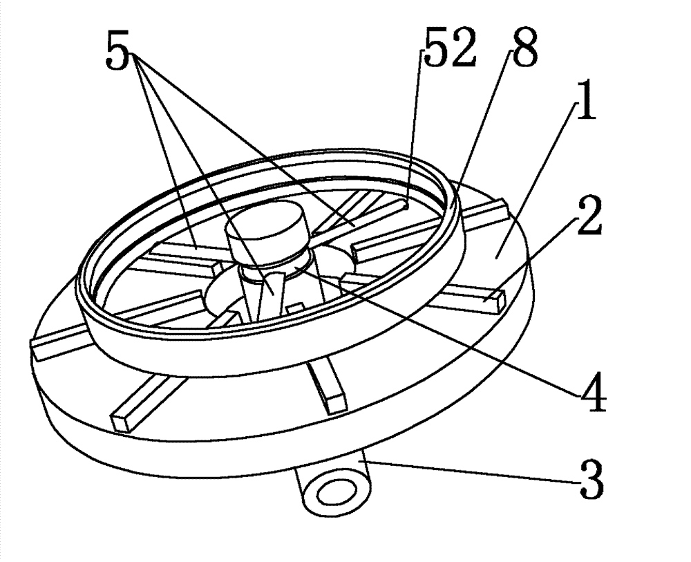
图4是本实用新型的实施例中喷气式旋翼的结构示意图; Fig. 4 is the structural representation of jet rotor in the embodiment of the present utility model;
图5是本实用新型的实施例中喷出的气流分解原理图; Fig. 5 is the principle diagram of the airflow decomposition ejected in the embodiment of the present utility model;
图6是本实用新型的实施例中气场的工作原理图; Fig. 6 is the working principle diagram of the gas field in the embodiment of the utility model;
图7是本实用新型的实施例的应用示意图。 Fig. 7 is a schematic diagram of the application of the embodiment of the present invention.
具体实施方式 Detailed ways
定心装置的实施例,如图1-7所示,包括用于放置零件的定心平台1,定心平台1具有使用时与水平面平齐的放置平面,定心平台1上设置有转动轴线与放置平面垂直的喷气式旋翼,所述的喷气式旋翼包括转轴3,转轴3上通过轴套4设置有沿转轴径向延伸的支撑体5,支撑体5为沿转轴3的圆周方向均匀分布的三个具有流线型的翼板,转轴3及支撑体5内部设置有相互连通的气道,所述的气道包括轴套4的内壁上设置的导气环槽41,支撑体与转轴上均设置有与导气环槽相连通的通道,支撑体5的悬伸端均设置有与其上设置的通道51相通的喷气口52,且喷气口52设置在支撑体圆周方向的同一侧,且具转轴中心线的距离均相等,喷气口52与气道连通的喷气道53与对应的喷气口过中心的直线均具有相同的一个夹角,支撑体5在旋转时气流流经支撑体5的原理图,流线型设计能够使气流更稳定的流到支撑体尾部,减少气流的分离,进而减少了真空区,所以此结构的支撑体能够减少在旋转的过程中空气的阻力,转轴3上设置有用于将轴套4上、下方向限位的上、下限位沿,定心平台1上设置有从喷气式旋翼的转轴3处向四周辐射延伸设置并沿圆周方向均布的用于支撑零件的支撑凸条2,支撑凸条2的顶面形成所述的放置平面。
The embodiment of the centering device, as shown in Figures 1-7, includes a
上述实施例在使用时,如图5-7所示,当高速气流从喷气口斜射出时,喷出的气流的分解原理如图5所示,可以把气流Q分解为沿旋翼圆周运动轨迹的切线方向Q1和法向方向Q2,沿切线方向Q1的气流会对旋翼产生反作用力,推动旋翼高速逆时针旋转,随着旋翼的高速旋转,法向方向的分支气流Q2沿旋翼圆周运动轨迹6会产生持续等量且沿其轨迹的圆周方向均匀分布的气流,从而产生稳定的气流场如图6所示,图中的圆周方向的箭头为翼板旋转方向,此气流场中心即为旋翼回转体的中心,也是整个定心装置的基准中心,如图7所示,将零件8放置在定心平台上,此时高压气体从进气管进入,从出气孔进入到导气环槽内,在由导气环槽进入到喷气式旋翼气道,从喷气口高速喷出,因Q1气体的反作用力使喷气式旋翼开始旋转,产生气流场,若工件中心与基准中心不重合,则工件受力必然不平衡,从而产生运动,只有工件运动到工件中心与基准中心完全重合时,整个工件才会受力平衡停止运动,从而达到自动定心的目的,工件定心原理如图6所示,整个定心过程,只需待测件放置在平台上,之后自动完成定心过程,无需人工辅助,减少了人工误差,采用喷气式旋翼装置定心,使待测件在定心过程中,零件整体受力较小,不易产生形变,减少废品率,整个定心装置定心过程耗时少,对操作工人要求程度不高,卫生环保,间接提高了利润率。
When the above-mentioned embodiment is in use, as shown in Figure 5-7, when the high-speed airflow is obliquely ejected from the air nozzle, the decomposition principle of the ejected airflow is as shown in Figure 5, and the airflow Q can be decomposed into components along the circular motion track of the rotor. The tangential direction Q1 and the normal direction Q2, the airflow along the tangential direction Q1 will produce a reaction force on the rotor, pushing the rotor to rotate counterclockwise at high speed. Produce continuous and equal airflow uniformly distributed along the circumferential direction of its trajectory, thereby generating a stable airflow field as shown in Figure 6. The arrow in the circumferential direction in the figure is the direction of blade rotation, and the center of this airflow field is the rotor rotor The center of the center is also the reference center of the entire centering device. As shown in Figure 7, the
在其它的实施例中, 定心平台上还可以不设置支撑凸条,直接将零件放置到定心平台上即可。 In other embodiments, the centering platform may not be provided with supporting ribs, and the parts may be directly placed on the centering platform.
在其它的实施例中,所述的转轴还可以与支撑体固定连接。 In other embodiments, the rotating shaft can also be fixedly connected with the supporting body.
在其它的实施例中,所述的支撑体的形状还可以为普通的连杆状或圆盘。 In other embodiments, the shape of the support body can also be a common rod shape or a disc.
在其它的实施例中,所示的喷气式旋翼上的翼板的个数不局限于上述的三个,因此本领域的技术人员还可以根据需要设置成两个或三个以上。 In other embodiments, the number of wing plates on the jet rotor shown is not limited to the above three, so those skilled in the art can also set it to two or more as required.
Claims (3)
Priority Applications (1)
| Application Number | Priority Date | Filing Date | Title |
|---|---|---|---|
| CN2012200026563U CN202494436U (en) | 2012-01-05 | 2012-01-05 | Centering device |
Applications Claiming Priority (1)
| Application Number | Priority Date | Filing Date | Title |
|---|---|---|---|
| CN2012200026563U CN202494436U (en) | 2012-01-05 | 2012-01-05 | Centering device |
Publications (1)
| Publication Number | Publication Date |
|---|---|
| CN202494436U true CN202494436U (en) | 2012-10-17 |
Family
ID=47000661
Family Applications (1)
| Application Number | Title | Priority Date | Filing Date |
|---|---|---|---|
| CN2012200026563U Expired - Lifetime CN202494436U (en) | 2012-01-05 | 2012-01-05 | Centering device |
Country Status (1)
| Country | Link |
|---|---|
| CN (1) | CN202494436U (en) |
Cited By (1)
| Publication number | Priority date | Publication date | Assignee | Title |
|---|---|---|---|---|
| CN102679920A (en) * | 2012-01-05 | 2012-09-19 | 河南科技大学 | Centering device |
-
2012
- 2012-01-05 CN CN2012200026563U patent/CN202494436U/en not_active Expired - Lifetime
Cited By (1)
| Publication number | Priority date | Publication date | Assignee | Title |
|---|---|---|---|---|
| CN102679920A (en) * | 2012-01-05 | 2012-09-19 | 河南科技大学 | Centering device |
Similar Documents
| Publication | Publication Date | Title |
|---|---|---|
| CN103394880A (en) | Large-sized circulating pump impeller forming method through swing welding | |
| CN201664801U (en) | Special cutting tools for flanges | |
| CN205074557U (en) | A six point location turning attachments of feeling relieved certainly for rotating member is cast to essence | |
| CN202494436U (en) | Centering device | |
| CN103161515B (en) | Airflow driving device | |
| CN205940348U (en) | Support lateral runout examines utensil | |
| CN204666078U (en) | Roundness measurement frock inside and outside a kind of ring magnet | |
| CN203141227U (en) | Ultra-precise air-floatation adjusting rotary table | |
| CN106370412A (en) | A turbine test bench | |
| CN207377968U (en) | A kind of air-float turntable | |
| CN103615466B (en) | A kind of highi degree of accuracy air floating shaft system gas supply mechanism | |
| CN102679920B (en) | a centering device | |
| CN204988627U (en) | Impeller dynamic balance test fixture | |
| CN206479314U (en) | A turbine test bench | |
| CN206974487U (en) | A kind of gas turbine meter | |
| CN204221007U (en) | A kind of vertical air hydrostatic spindle | |
| CN204479002U (en) | A kind of roll centre hole accuracy detecting device | |
| CN202224916U (en) | Three-dimensional space positioning assembly tool for mixed-flow runner blade | |
| CN206959738U (en) | Automobile pair silencer forming detection device | |
| CN203231731U (en) | A detector for a wind turbine blade | |
| CN100457342C (en) | Method and device for water distributing ring circular base type joint-boring process | |
| CN206071928U (en) | A kind of improved centrifugal blower rotating stall experimental provision | |
| CN106246587B (en) | A kind of improved centrifugal blower rotating stall experimental provision and its detection method | |
| CN207687002U (en) | High-precision water pump bath scaled model experimental device | |
| CN203432509U (en) | Testing fixture for steering wheel hub |
Legal Events
| Date | Code | Title | Description |
|---|---|---|---|
| C14 | Grant of patent or utility model | ||
| GR01 | Patent grant | ||
| AV01 | Patent right actively abandoned |
Granted publication date: 20121017 Effective date of abandoning: 20140521 |
|
| RGAV | Abandon patent right to avoid regrant |