CN202494082U - Tubular fluorescent light - Google Patents
Tubular fluorescent light Download PDFInfo
- Publication number
- CN202494082U CN202494082U CN2012201030956U CN201220103095U CN202494082U CN 202494082 U CN202494082 U CN 202494082U CN 2012201030956 U CN2012201030956 U CN 2012201030956U CN 201220103095 U CN201220103095 U CN 201220103095U CN 202494082 U CN202494082 U CN 202494082U
- Authority
- CN
- China
- Prior art keywords
- fluorescent lamp
- transparent shell
- tube
- tubular type
- power source
- Prior art date
- Legal status (The legal status is an assumption and is not a legal conclusion. Google has not performed a legal analysis and makes no representation as to the accuracy of the status listed.)
- Expired - Fee Related
Links
Images

Landscapes
- Arrangement Of Elements, Cooling, Sealing, Or The Like Of Lighting Devices (AREA)
Abstract
A tubular fluorescent light comprises a transparent tube shell, a light tube arranged inside the transparent tube shell and end caps arranged on two sides of the transparent tube shell. The light tube is fixedly arranged inside the transparent tube shell through a light tube holder, the light tube holder comprises a power source portion arranged on one side and a light tube portion arranged on the other side, and the power source portion is provided with a hollow power source cavity. The tubular fluorescent light is even in inner temperature in the process of working and free of over-high temperature partly, and components are long in service life.
Description
Technical field
The utility model relates to a kind of lighting apparatus, relates in particular to a kind of tubular type fluorescent lamp.
Background technology
The fluorescent lamp that uses in the daily life at present scarcely possesses the waterproof and dustproof function; Can't adapt to some special occasions; Like humid environment or more spinning, the textile industry of dust; Conventional fluorescent lamp often used one month, even shorter time will change, and is with high costs.
Patent announcement CN2677743 discloses a kind of double hose fluorescent lamp of explosion-proof waterproof, mainly comprises an explosive-proof protector pipe, two fluorescent tubes.The relative prior art of double hose fluorescent lamp of this utility model also is provided with sealing device because of it and protection tube has explosion-proof, waterproof and dustproof function except that increasing brightness of illumination and dependability.
This explosion-proof, waterproof fluorescent lamp is fitted occasion to be increased greatly; But fluorescent lamp in the course of the work; The part of fluorescent lamp can produce a large amount of heats, be completely enclosed within fluorescent lamp in the transparent shell after, these heats can't in time be distributed; Can cause the light fixture local temperature too high, bring infringement to light fixture.
The utility model content
The utility model is for solving the prior art problem, and a kind of totally enclosed tubular type fluorescent lamp of safe and reliable, water proof and dust proof is provided.
The technical scheme of the utility model is: a kind of tubular type fluorescent lamp; Comprise transparent shell; Be arranged at fluorescent tube in this transparent shell and the end cap that is arranged at these transparent shell two ends; Said fluorescent tube is fixedly installed in the said transparent shell through tube face, and said tube face comprises power supply unit that is positioned at a side and the fluorescent tube portion that is positioned at opposite side, and said power supply unit is provided with the power source cavity of hollow.
As preferably, said power source cavity in a tubular form, and direction is parallel with fluorescent tube; These power source cavity two ends have air vent.
When fluorescent lamp operation; Power supply is one of the highest point of transparent shell internal temperature, and the power source cavity that the power supply baffle plate surrounds is formed an air channel, makes air in the inner realization of transparent shell, to circulate; Flow air is cooled off power supply, prolongs power supply service life; Flow air carries out the heat in the transparent shell evenly to make light fixture can not produce localized hyperthermia simultaneously, has avoided the parts damages that can generate heat.
As preferably, the both sides of said power source cavity are equipped with fin.
As preferably, the front of said tube face is provided with reflector layer.
As preferably, said reflector layer is reflecting coating or reflecting piece.
As preferably, said power source cavity and fin have the radian that cooperates with said transparent tube shell facies.
Through tube face fluorescent tube and ballast are separated, reduce the heat of light fixture generation and the heat of power supply generation and influence each other; Tube face can also reflect the light that fluorescent tube sends, and the light that makes fluorescent tube send is more concentrated, and utilization rate is higher.
As preferably, said transparent shell is provided with jockey.
As preferably, said jockey comprises and is arranged at the fixedly inner radially evagination circle of end cap of said transparent shell two ends, and is arranged at the link plate with holes on the said radially evagination circle.
As preferably, said jockey comprises the contiguous block that is arranged at said transparent shell middle part.
Jockey is used for fluorescent lamp is installed on equipment, and jockey is arranged at the fluorescent tube center, then is convenient to install, and shortcoming is that lamp tube ends is easy to rock; Jockey is arranged at lamp tube ends, and then lamp tube ends fixation is difficult for rocking, and shortcoming is the operative employee in case the middle part of careless collision fluorescent tube, then fluorescent tube very easily therefrom between fracture.
As preferably; Said tube face two ends are provided with two lamp tube end socket in order to the grafting fluorescent tube; Described lamp tube end socket comprises socket and jack housing; Said jack housing comprises the socket end and the inserted terminal that is plugged in the electronic device installation cavity of the said socket of socket, also offers the elasticity positioning convex on the said jack housing, offers the locating hole that cooperates with said elasticity positioning convex on the said electronic device installation cavity.
In sum, internal temperature is even during the work of the utility model light fixture, and it is too high can not local temperature to occur, the parts long service life.
Description of drawings
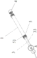
Fig. 1 is the utility model embodiment one perspective view;
Fig. 2 is an A place partial enlarged drawing among Fig. 1;
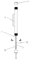
Fig. 3 is the utility model embodiment one side view;
Fig. 4 is a B-B anatomical structure sketch map among Fig. 3;
Fig. 5 is the utility model embodiment two side views;
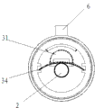
Fig. 6 is a C-C anatomical structure sketch map among Fig. 5.
Among the figure, 1, transparent shell, 2, fluorescent tube, 3, tube face, 31, power supply unit; 311, air vent, 312, jack housing, 313, socket, 3121, socket end, 3122, inserted terminal; 3123, locating hole, 3124, elastic bumps, 32, fluorescent tube portion, 33, fin, 34, reflecting piece; 4, end cap, 5, evagination circle radially, 51, link plate with holes, 6, contiguous block.
The specific embodiment
With embodiment the utility model is described further below.
Embodiment one:
A kind of tubular type fluorescent lamp comprises transparent shell 1, is arranged at fluorescent tube 2 in this transparent shell 1 and the end cap 4 that is arranged at these transparent shell 1 two ends; Fluorescent tube 2 is fixedly installed in the transparent shell 1 through tube face 3; Tube face 3 comprises power supply unit 31 that is positioned at a side and the fluorescent tube portion 32 that is positioned at opposite side, and power supply unit 31 is provided with the power source cavity of hollow, and power source cavity in a tubular form; And direction is parallel with fluorescent tube 2, and these power source cavity two ends have air vent 311.The both sides of power source cavity are equipped with fin 33, and power source cavity and fin 33 have the radian that matches with transparent shell 1, and the front of tube face 3 scribbles reflecting coating.Transparent shell 1 is provided with jockey, and jockey comprises and be arranged at the fixedly inner radially evagination circle 5 of end cap 4 of transparent shell 1 two ends, and is arranged at the link plate with holes 51 on the evagination circle 5 radially.Tube face 3 two ends are provided with two fluorescent tube 2 end seats in order to grafting fluorescent tube 2; Fluorescent tube 2 end seats comprise socket 313 and jack housing 312; Jack housing 312 comprises socket end 3121 of overlapping combination hub 313 and the inserted terminal 3122 that is plugged in the electronic device installation cavity; Also offer elastic bumps 3124 on the jack housing 312, offer the locating hole 3123 that cooperates with elastic bumps 3124 on the electronic device installation cavity.
Embodiment two:
A kind of tubular type fluorescent lamp comprises transparent shell 1, is arranged at fluorescent tube 2 in this transparent shell 1 and the end cap 4 that is arranged at these transparent shell 1 two ends; Fluorescent tube 2 is fixedly installed in the transparent shell 1 through tube face 3; Tube face 3 comprises power supply unit 31 that is positioned at a side and the fluorescent tube portion 32 that is positioned at opposite side, and power supply unit 31 is provided with the power source cavity of hollow, and power source cavity in a tubular form; And direction is parallel with fluorescent tube 2, and these power source cavity two ends have air vent 311.The both sides of power source cavity are equipped with fin 33, and power source cavity and fin 33 have the radian that matches with transparent shell 1, and reflecting piece 34 is posted in the front of tube face 3.Transparent shell 1 is provided with jockey, and jockey is the contiguous block 6 that is pasted on transparent shell 1 middle part.Tube face 3 two ends are provided with two fluorescent tube 2 end seats in order to grafting fluorescent tube 2; Fluorescent tube 2 end seats comprise socket 313 and jack housing 312; Jack housing 312 comprises socket end 3121 of overlapping combination hub 313 and the inserted terminal 3122 that is plugged in the electronic device installation cavity; Also offer elastic bumps 3124 on the jack housing 312, offer the locating hole 3123 that cooperates with elastic bumps 3124 on the electronic device installation cavity.
Claims (10)
1. tubular type fluorescent lamp; Comprise transparent shell (1); Be arranged at fluorescent tube (2) in this transparent shell (1) and the end cap (4) that is arranged at these transparent shell (1) two ends; Said fluorescent tube (2) is fixedly installed in the said transparent shell (1) through tube face (3), it is characterized in that: said tube face (3) comprises power supply unit (31) that is positioned at a side and the fluorescent tube portion (32) that is positioned at opposite side, and said power supply unit (31) is provided with the power source cavity of hollow.
2. according to the said tubular type fluorescent lamp of claim 1, it is characterized in that: said power source cavity in a tubular form, and direction is parallel with fluorescent tube (2); These power source cavity two ends have air vent (311).
3. according to the said tubular type fluorescent lamp of claim 2, it is characterized in that: the both sides of said power source cavity are equipped with fin (33).
4. according to the said tubular type fluorescent lamp of claim 3, it is characterized in that: the front of said tube face (3) is provided with reflector layer.
5. according to the said tubular type fluorescent lamp of claim 4, it is characterized in that: said reflector layer is reflecting coating or reflecting piece (34).
6. according to any said tubular type fluorescent lamp of claim 3 ~ 5, it is characterized in that: said power source cavity and fin (33) have the radian that matches with said transparent shell (1).
7. according to the said tubular type fluorescent lamp of claim 1, it is characterized in that: said transparent shell (1) is provided with jockey.
8. according to the said tubular type fluorescent lamp of claim 7; It is characterized in that: said jockey comprises and is arranged at the fixedly inner radially evagination circle (5) of end cap (4) of said transparent shell (1) two ends, and is arranged at the link plate with holes (51) on the said radially evagination circle (5).
9. according to the said tubular type fluorescent lamp of claim 7, it is characterized in that: said jockey comprises the contiguous block (6) that is arranged at said transparent shell (1) middle part.
10. according to the said tubular type fluorescent lamp of claim 1; It is characterized in that: said tube face (3) two ends are provided with two fluorescent tubes in order to grafting fluorescent tube (2) (2) end seat; Described fluorescent tube (2) end seat comprises socket (313) and jack housing (312); Said jack housing (312) comprises the socket end (3121) of the said socket of socket (313) and is plugged on the inserted terminal (3122) in the electronic device installation cavity; Also offer elastic bumps (3124) on the said jack housing (312), offer the locating hole (3123) that cooperates with said elastic bumps (3124) on the said electronic device installation cavity.
Priority Applications (1)
| Application Number | Priority Date | Filing Date | Title |
|---|---|---|---|
| CN2012201030956U CN202494082U (en) | 2012-03-19 | 2012-03-19 | Tubular fluorescent light |
Applications Claiming Priority (1)
| Application Number | Priority Date | Filing Date | Title |
|---|---|---|---|
| CN2012201030956U CN202494082U (en) | 2012-03-19 | 2012-03-19 | Tubular fluorescent light |
Publications (1)
| Publication Number | Publication Date |
|---|---|
| CN202494082U true CN202494082U (en) | 2012-10-17 |
Family
ID=47000307
Family Applications (1)
| Application Number | Title | Priority Date | Filing Date |
|---|---|---|---|
| CN2012201030956U Expired - Fee Related CN202494082U (en) | 2012-03-19 | 2012-03-19 | Tubular fluorescent light |
Country Status (1)
| Country | Link |
|---|---|
| CN (1) | CN202494082U (en) |
Cited By (1)
| Publication number | Priority date | Publication date | Assignee | Title |
|---|---|---|---|---|
| CN103471006A (en) * | 2013-09-12 | 2013-12-25 | 王培清 | Special safelight for water jet loom |
-
2012
- 2012-03-19 CN CN2012201030956U patent/CN202494082U/en not_active Expired - Fee Related
Cited By (1)
| Publication number | Priority date | Publication date | Assignee | Title |
|---|---|---|---|---|
| CN103471006A (en) * | 2013-09-12 | 2013-12-25 | 王培清 | Special safelight for water jet loom |
Similar Documents
| Publication | Publication Date | Title |
|---|---|---|
| CN202494082U (en) | Tubular fluorescent light | |
| CN204141291U (en) | A kind of LED corn lamp | |
| CN201944628U (en) | LED(light-emitting diode)lamp | |
| CN202580763U (en) | Novel light-emitting diode (LED) fluorescent tube | |
| CN203907395U (en) | Independently-installable LED lamp with integrated light source and lamp | |
| CN203868791U (en) | Lamp body device | |
| CN204201715U (en) | A kind of LED road lighting lamp | |
| CN203363978U (en) | Novel LED lampshade | |
| CN207438202U (en) | A kind of LED light with water-proof function | |
| CN202082679U (en) | LED lamp bulb | |
| CN204665079U (en) | A kind of external heat radiation formula street lamp | |
| CN202195371U (en) | Driven-radiating type high-power light-emitting diode (LED) lamp | |
| CN203880514U (en) | IP67 touch LED machine tool working lamp | |
| CN202203736U (en) | Fluorescent lamp | |
| CN208504138U (en) | A kind of ceiling lamp | |
| CN202747025U (en) | LED (light emitting diode) lamp | |
| CN202947043U (en) | Light-emitting diode (LED) ceiling lamp with external power supply | |
| CN202708754U (en) | Irradiation-angle-adjustable LED (light-emitting diode) lamp | |
| CN202769353U (en) | Butterfly shape reflection energy-saving lamp | |
| CN202274394U (en) | Direct-lighting type lens front fog lamp | |
| CN202040635U (en) | Light-emitting diode (LED) combined bracket lamp | |
| CN201368376Y (en) | LED streetlight with high luminous efficiency | |
| CN201141575Y (en) | LED daylight lamp | |
| CN207298609U (en) | A kind of LED light-guiding lamps | |
| CN204227235U (en) | Lamp with concealed support |
Legal Events
| Date | Code | Title | Description |
|---|---|---|---|
| C14 | Grant of patent or utility model | ||
| GR01 | Patent grant | ||
| CF01 | Termination of patent right due to non-payment of annual fee |
Granted publication date: 20121017 Termination date: 20150319 |
|
| EXPY | Termination of patent right or utility model |