CN202494073U - Lighting circuit and lighting device - Google Patents
Lighting circuit and lighting device Download PDFInfo
- Publication number
- CN202494073U CN202494073U CN2012200494366U CN201220049436U CN202494073U CN 202494073 U CN202494073 U CN 202494073U CN 2012200494366 U CN2012200494366 U CN 2012200494366U CN 201220049436 U CN201220049436 U CN 201220049436U CN 202494073 U CN202494073 U CN 202494073U
- Authority
- CN
- China
- Prior art keywords
- lighting
- control device
- circuit
- time control
- lamps
- Prior art date
- Legal status (The legal status is an assumption and is not a legal conclusion. Google has not performed a legal analysis and makes no representation as to the accuracy of the status listed.)
- Expired - Fee Related
Links
- 239000002699 waste material Substances 0.000 abstract description 5
- 230000005611 electricity Effects 0.000 abstract description 4
- 230000007774 longterm Effects 0.000 abstract description 3
- 238000000034 method Methods 0.000 description 5
- 241001465382 Physalis alkekengi Species 0.000 description 1
- 230000009286 beneficial effect Effects 0.000 description 1
- 238000010586 diagram Methods 0.000 description 1
- 238000004519 manufacturing process Methods 0.000 description 1
- 238000012986 modification Methods 0.000 description 1
- 230000004048 modification Effects 0.000 description 1
- 230000007935 neutral effect Effects 0.000 description 1
Images

Classifications
-
- Y—GENERAL TAGGING OF NEW TECHNOLOGICAL DEVELOPMENTS; GENERAL TAGGING OF CROSS-SECTIONAL TECHNOLOGIES SPANNING OVER SEVERAL SECTIONS OF THE IPC; TECHNICAL SUBJECTS COVERED BY FORMER USPC CROSS-REFERENCE ART COLLECTIONS [XRACs] AND DIGESTS
- Y02—TECHNOLOGIES OR APPLICATIONS FOR MITIGATION OR ADAPTATION AGAINST CLIMATE CHANGE
- Y02B—CLIMATE CHANGE MITIGATION TECHNOLOGIES RELATED TO BUILDINGS, e.g. HOUSING, HOUSE APPLIANCES OR RELATED END-USER APPLICATIONS
- Y02B20/00—Energy efficient lighting technologies, e.g. halogen lamps or gas discharge lamps
- Y02B20/40—Control techniques providing energy savings, e.g. smart controller or presence detection
Landscapes
- Circuit Arrangement For Electric Light Sources In General (AREA)
Abstract
本实用新型公开了一种照明电路和照明装置,其中,照明电路包括电源开关与照明灯具,以及串联在所述电源开关与所述照明灯具之间的时控装置,用于控制所述照明灯具定时开关。在照明电路中串联时控装置用于控制灯具的开启和关闭,这样可以根据需要控制灯具的开启和关闭,防止电量的浪费,无需人工对照明灯具进行管理,且可减少灯具因长时间不间断工作而造成的设备元器件的损坏。
The utility model discloses a lighting circuit and a lighting device, wherein the lighting circuit includes a power switch and a lighting fixture, and a time control device connected in series between the power switch and the lighting fixture, and is used to control the lighting fixture Set open close. In the lighting circuit, the time control device is connected in series to control the opening and closing of the lamps, so that the opening and closing of the lamps can be controlled according to the needs, to prevent the waste of electricity, and there is no need to manually manage the lighting lamps, and it can reduce the lamps due to long-term uninterrupted Damage to equipment components caused by work.
Description
技术领域 technical field
本实用新型涉及照明控制领域,尤其涉及一种照明电路及一种照明装置。The utility model relates to the field of lighting control, in particular to a lighting circuit and a lighting device.
背景技术 Background technique
目前工厂中使用的照明灯具多为人工控制开关,这样难免出现一些犹豫工作人员的疏忽所造成的能源浪费等问题,例如在白天没有使用照明的情况下未能及时关闭使得照明灯具一直开启,从而造成极大的电力浪费,且灯具长时间不间断工作可能会造成设备元器件的损坏。At present, most of the lighting fixtures used in the factory are manually controlled switches, so it is inevitable that there will be some problems such as energy waste caused by the negligence of hesitant staff. It causes a great waste of electricity, and the long-term uninterrupted operation of the lamp may cause damage to the equipment components.
实用新型内容 Utility model content
本实用新型要解决的主要技术问题是,提供一种照明电路及一种照明装置,能定时使用以避免电力浪费。The main technical problem to be solved by the utility model is to provide a lighting circuit and a lighting device, which can be used regularly to avoid power waste.
为解决上述技术问题,本实用新型提供一种照明电路,包括电源开关与照明灯具,还包括:串联在所述电源开关与所述照明灯具之间的时控装置,用于控制所述照明灯具定时开关。In order to solve the above technical problems, the utility model provides a lighting circuit, including a power switch and a lighting fixture, and also includes: a time control device connected in series between the power switch and the lighting fixture, used to control the lighting fixture Set open close.
一种实施例中,所述时控装置为机械式定时器。In one embodiment, the time control device is a mechanical timer.
另一种实施例中,所述时控装置为单片机控制式定时器。In another embodiment, the time control device is a timer controlled by a single chip microcomputer.
所述时控装置安装在配电箱内。The time control device is installed in the distribution box.
所述电源开关安装在所述配电箱内。The power switch is installed in the distribution box.
所述照明电路还包括连接线路,所述配电箱内的电路与所述电源开关、所述时控装置、所述照明灯具由所述连接线路连接形成连接回路。The lighting circuit also includes a connecting line, and the circuit in the distribution box is connected with the power switch, the time control device, and the lighting lamp by the connecting line to form a connecting circuit.
相应地,本实用新型实施例还提供一种照明装置,包括灯具主体和控制所述灯具主体的开关装置,还包括用于控制所述开关装置定时开关的时控装置,所述时控装置串联在所述灯具主体和所述开关装置之间。Correspondingly, the embodiment of the utility model also provides a lighting device, which includes a lamp body and a switch device for controlling the lamp body, and also includes a time control device for controlling the timing switch of the switch device, and the time control device is connected in series between the light fixture body and the switchgear.
一种实施例中,所述时控装置为机械式定时器。In one embodiment, the time control device is a mechanical timer.
另一种实施例中,所述时控装置为单片机控制式定时器。In another embodiment, the time control device is a timer controlled by a single chip microcomputer.
本实用新型的有益效果是:在照明电路中串联时控装置用于控制灯具的开启和关闭,这样可以根据需要控制灯具的开启和关闭,防止电量的浪费,无需人工对照明灯具进行管理,且可减少灯具因长时间不间断工作而造成的设备元器件的损坏。The beneficial effect of the utility model is: the time control device is connected in series in the lighting circuit to control the opening and closing of the lamps, so that the opening and closing of the lamps can be controlled according to the needs, and the waste of electricity can be prevented, and there is no need to manually manage the lighting lamps, and It can reduce the damage of equipment components caused by long-term uninterrupted work of lamps and lanterns.
附图说明 Description of drawings
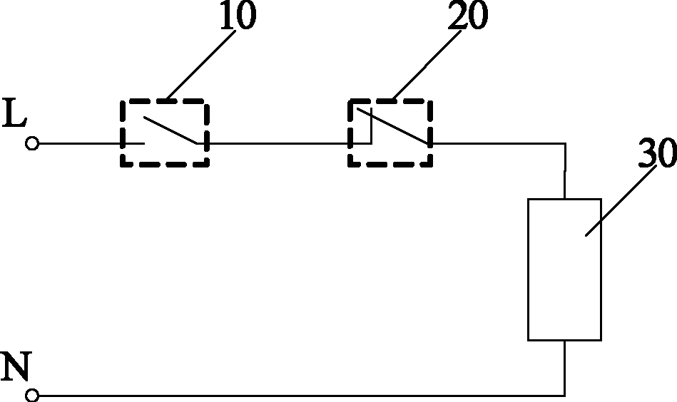
图1为本实用新型一种实施例的照明电路原理示意图。Fig. 1 is a schematic diagram of the principle of the lighting circuit of an embodiment of the present invention.
具体实施方式 Detailed ways
下面通过具体实施方式结合附图对本实用新型作进一步详细说明。The utility model will be described in further detail below through specific embodiments in conjunction with the accompanying drawings.
如图1所示,照明电路的一种实施例包括:电源开关10、时控装置20和照明灯具30;其中,时控装置20串联在电源开关10和照明灯具30之间,用于控制照明灯具30定时开启和关闭。As shown in Figure 1, an embodiment of the lighting circuit includes: a
时控装置20在具体实现时,可为机械式定时器或单片机控制式定时器。机械式定时器的实现可采用常用的机械式实现方法,例如现有对电风扇进行定时设置的定时器。单片机控制式定时器的实现同样可采用常用的单片机控制方法来实现。这里不对这些常用方法详述。The
实施例中,时控装置20可安装在配电箱内,由配电箱支撑固定时控装置;电源开关也可安装在配电箱内,由配电箱统一进行管理。配电箱内的电路如控制电路等由连接线路将电源开关、时控装置、照明灯具等连接起来从而形成连接回路。In the embodiment, the
以对某电池生产工厂的照明控制为例,可以通过本实用新型实施例的照明电路,对照明灯具加装时控装置,定时开启与关闭灯具,以实现节约用电的目的。具体实现时,在厂区所有照明灯具的控制电路中串联时控装置(定时器),根据所需要使用的时间和关闭时间对时控装置进行时间设定,利用时控装置来分时段控制照明灯具的工作。通常厂区所有照明灯具的控制电路集中在配电箱,在加装时控装置时,可以将时控装置安装在配电箱内,由配电箱支撑固定时控装置,时控装置串联在线路中通过设定时间段来控制灯具的开启和关闭,再经线路连接灯具使灯具工作形成完整回路(如电源开关端接到火线L,灯具的一端接到零线N),从而保障正常灯具等的工作。Taking the lighting control of a battery production factory as an example, the lighting circuit of the embodiment of the present invention can be used to install a time control device on the lighting lamps to turn on and off the lamps at regular intervals to achieve the purpose of saving electricity. In the specific implementation, the time control device (timer) is connected in series in the control circuit of all lighting fixtures in the factory, and the time control device is set according to the required use time and closing time, and the time control device is used to control the lighting fixtures in different periods work. Usually the control circuits of all lighting fixtures in the factory are concentrated in the distribution box. When installing the time control device, the time control device can be installed in the distribution box, and the time control device is supported and fixed by the distribution box. The time control device is connected in series to the line. In the system, the opening and closing of the lamps are controlled by setting the time period, and then the lamps are connected to the lamps to form a complete circuit (such as the end of the power switch is connected to the live line L, and one end of the lamp is connected to the neutral line N), so as to ensure normal lamps, etc. work.
本实用新型实施例的照明电路能适用于所有长时间不间断工作的灯具,通过采用分时段工作的方式,利用时控装置的自动控制特性,对节约电力、减少元器件损耗起到了很大作用。The lighting circuit of the embodiment of the utility model can be applied to all lamps that work uninterruptedly for a long time. By adopting the mode of working in different periods and using the automatic control characteristics of the time control device, it has played a great role in saving power and reducing the loss of components. .
基于此,本实用新型实施例相应地提供一种照明装置,该照明装置包括灯具主体、控制该灯具主体的开关装置、以及用于控制开关装置定时开关的时控装置。该时控装置串联在灯具主体和开关装置之间。时控装置可以为机械式定时器或单片机控制式定时器,具体定时器的实现可采用常用的定时器设计方法,在此不作限定。Based on this, an embodiment of the utility model provides a lighting device correspondingly, the lighting device includes a lamp body, a switch device for controlling the lamp body, and a time control device for controlling a timing switch of the switch device. The time control device is connected in series between the main body of the lamp and the switch device. The time control device can be a mechanical timer or a single-chip microcomputer-controlled timer, and the realization of the specific timer can adopt a commonly used timer design method, which is not limited here.
上述实施例只是本实用新型的举例,尽管为说明目的公开了本实用新型的最佳实施例和附图,但是本领域的技术人员可以理解:在不脱离本实用新型及所附的权利要求的精神和范围内,各种替换、变化和修改都是可能的。因此,本实用新型不应局限于最佳实施例和附图所公开的内容。Above-mentioned embodiment is only the example of the present utility model, although the preferred embodiment of the present utility model and accompanying drawing are disclosed for the purpose of illustration, those skilled in the art can understand: without departing from the present utility model and the appended claims Various alternatives, changes and modifications are possible within the spirit and scope. Therefore, the utility model should not be limited to the content disclosed in the preferred embodiment and accompanying drawings.
Claims (9)
Priority Applications (1)
| Application Number | Priority Date | Filing Date | Title |
|---|---|---|---|
| CN2012200494366U CN202494073U (en) | 2012-02-15 | 2012-02-15 | Lighting circuit and lighting device |
Applications Claiming Priority (1)
| Application Number | Priority Date | Filing Date | Title |
|---|---|---|---|
| CN2012200494366U CN202494073U (en) | 2012-02-15 | 2012-02-15 | Lighting circuit and lighting device |
Publications (1)
| Publication Number | Publication Date |
|---|---|
| CN202494073U true CN202494073U (en) | 2012-10-17 |
Family
ID=47000298
Family Applications (1)
| Application Number | Title | Priority Date | Filing Date |
|---|---|---|---|
| CN2012200494366U Expired - Fee Related CN202494073U (en) | 2012-02-15 | 2012-02-15 | Lighting circuit and lighting device |
Country Status (1)
| Country | Link |
|---|---|
| CN (1) | CN202494073U (en) |
-
2012
- 2012-02-15 CN CN2012200494366U patent/CN202494073U/en not_active Expired - Fee Related
Similar Documents
| Publication | Publication Date | Title |
|---|---|---|
| CN105388803A (en) | Double-control switch | |
| CN202494073U (en) | Lighting circuit and lighting device | |
| CN105142277A (en) | Intelligent lighting control system and method for transformer substation | |
| CN105444101A (en) | Solar integrated lamp with infrared remote control | |
| CN202535599U (en) | Power carrier integrated controller for urban lighting | |
| CN204929367U (en) | A intelligent automatic control system for lighting system of thermal power factory | |
| CN203057636U (en) | A power-off self-locking switch | |
| CN202873158U (en) | Light-control fuzzy controller for street lamp | |
| CN202997697U (en) | Transformer station remote power-saving monitoring system | |
| CN203313473U (en) | Wired intelligent illumination control system | |
| CN202257121U (en) | Classroom energy-saving system | |
| CN204906790U (en) | A intelligent lighting control module for lighting control system of transformer substation | |
| CN201821538U (en) | Intelligent switching power supply control circuit for high-power LED lighting by time division and power division | |
| CN202799325U (en) | Intelligent sunset timing control device | |
| CN203349132U (en) | A rechargeable LED remote control downlight with backup power supply | |
| CN201298943Y (en) | Safe timing control circuit of a lighting lamp | |
| CN102843843A (en) | Intelligent control device of sunset timing sequence | |
| CN205305201U (en) | Data center light energy -saving control system | |
| CN205196055U (en) | Long -range unmanned on duty measurement system's lighting control system of mill | |
| CN201601662U (en) | light switch | |
| CN202261945U (en) | High-power LED lamp isolation high-voltage DC centralized control power supply device | |
| CN203219597U (en) | Integrated energy-saving high-pressure sodium lamp | |
| CN209659677U (en) | A kind of intelligent power | |
| CN201708981U (en) | Illumination circuit with timer | |
| CN205430725U (en) | Photoelectricity automatic control device |
Legal Events
| Date | Code | Title | Description |
|---|---|---|---|
| C14 | Grant of patent or utility model | ||
| GR01 | Patent grant | ||
| CF01 | Termination of patent right due to non-payment of annual fee |
Granted publication date: 20121017 Termination date: 20150215 |
|
| EXPY | Termination of patent right or utility model |