CN202494072U - Novel LED lamp - Google Patents
Novel LED lamp Download PDFInfo
- Publication number
- CN202494072U CN202494072U CN2012200053096U CN201220005309U CN202494072U CN 202494072 U CN202494072 U CN 202494072U CN 2012200053096 U CN2012200053096 U CN 2012200053096U CN 201220005309 U CN201220005309 U CN 201220005309U CN 202494072 U CN202494072 U CN 202494072U
- Authority
- CN
- China
- Prior art keywords
- led
- circuit board
- printed circuit
- pcb
- fuse
- Prior art date
- Legal status (The legal status is an assumption and is not a legal conclusion. Google has not performed a legal analysis and makes no representation as to the accuracy of the status listed.)
- Expired - Fee Related
Links
Images
Classifications
-
- Y—GENERAL TAGGING OF NEW TECHNOLOGICAL DEVELOPMENTS; GENERAL TAGGING OF CROSS-SECTIONAL TECHNOLOGIES SPANNING OVER SEVERAL SECTIONS OF THE IPC; TECHNICAL SUBJECTS COVERED BY FORMER USPC CROSS-REFERENCE ART COLLECTIONS [XRACs] AND DIGESTS
- Y02—TECHNOLOGIES OR APPLICATIONS FOR MITIGATION OR ADAPTATION AGAINST CLIMATE CHANGE
- Y02B—CLIMATE CHANGE MITIGATION TECHNOLOGIES RELATED TO BUILDINGS, e.g. HOUSING, HOUSE APPLIANCES OR RELATED END-USER APPLICATIONS
- Y02B20/00—Energy efficient lighting technologies, e.g. halogen lamps or gas discharge lamps
- Y02B20/40—Control techniques providing energy savings, e.g. smart controller or presence detection
Landscapes
- Illuminated Signs And Luminous Advertising (AREA)
- Non-Portable Lighting Devices Or Systems Thereof (AREA)
Abstract
本实用新型公开了一种新型LED灯,包括灯壳、LED单元,LED单元由至少一LED发光体、印刷电路板组成,印刷电路板包括温度感应装置、恒电流装置、保险丝、电源正负极线路,保险丝与印刷电路板上的一条电源正极线路相连接,线路温度超过预设温度时,自动熔断,恒电流装置通过保险丝与印刷电路板的电源正负极线路连接,温度感应装置与印刷电路板的电源正极线路连接,用于监测温度,在超过预设温度时,自动切断电源,减少LED输入信号干扰、使其信号稳定、成本更低,且在不影响视觉范围和散热效果的基础上更加轻薄,安装更加灵活。

The utility model discloses a novel LED lamp, which comprises a lamp housing and an LED unit. The LED unit is composed of at least one LED luminous body and a printed circuit board. The printed circuit board includes a temperature sensing device, a constant current device, a fuse, and positive and negative electrodes of a power supply. The fuse is connected to a positive power line on the printed circuit board. When the temperature of the line exceeds the preset temperature, it will automatically fuse. The constant current device is connected to the positive and negative power lines of the printed circuit board through the fuse. The temperature sensing device is connected to the printed circuit board The positive line connection of the power supply of the board is used to monitor the temperature. When the preset temperature is exceeded, the power supply is automatically cut off to reduce the interference of the LED input signal, make the signal stable, and lower the cost without affecting the visual range and heat dissipation effect. Thinner and lighter, more flexible installation.
Description
技术领域 technical field
本实用新型涉及LED领域,特别涉及一种新型LED灯。 The utility model relates to the field of LEDs, in particular to a novel LED lamp.
背景技术 Background technique
LED因发光效率高,节能省电,使用寿命长,可实现长期免维修,不含汞,无污染,环保,色温范围广,便于营造动态空间照明效果,可同时满足不同照明需要,在现今信息发达,科技日新的时代,电子显示装置扮演了相当重要的角色,如政府的政令倡导、企业形象及产品广告、舞台作秀实况、公共场所各类讯息指示等,都需通过形形色色的电子显示装置传递,以达到最佳的效果使 LED可以被广泛推广,因此对LED的要求也随之提高,现有技术中用来控制灯的驱动控制芯片一般需要四根控制信号线,所以用软线连接时,一般有两个输入头,两个输出头,电源接头和信号接头各一个,由于接头数量较多,使得接头故障率较高,可靠性较低,容易靠成短路,掉线等问题,四根信号相互干扰,影响正常使用,还会缩短灯的使用寿命。 LED has high luminous efficiency, energy saving, long service life, long-term maintenance-free, no mercury, no pollution, environmental protection, wide color temperature range, easy to create dynamic space lighting effects, and can meet different lighting needs at the same time. In today's information In the era of advanced technology and new technology, electronic display devices play a very important role, such as the government's policy advocacy, corporate image and product advertisements, live performances on the stage, and various information instructions in public places, etc., all need to be passed through various electronic display devices. In order to achieve the best effect, LED can be widely promoted, so the requirements for LED are also increased. In the prior art, the drive control chip used to control the lamp generally needs four control signal lines, so it is connected with a flexible wire. Generally, there are two input heads, two output heads, one power connector and one signal connector. Due to the large number of connectors, the failure rate of the connectors is high, the reliability is low, and it is easy to cause problems such as short circuits and dropped connections. The four signals interfere with each other, affecting normal use and shortening the service life of the lamp. the
实用新型内容 Utility model content
本实用新型的主要目的在于克服现有技术的不足,提供一种输入信号干扰少、信号稳定、成本更低,且在不影响视觉范围和散热效果的基础上更加轻薄,安装更加灵活。 The main purpose of the utility model is to overcome the deficiencies of the prior art, to provide a device with less input signal interference, stable signal, lower cost, lighter and thinner, and more flexible installation without affecting the visual range and heat dissipation effect.
为实现上述目的,本实用新型所采用了下述的技术方案:一种新型LED灯,包括灯壳、LED单元,LED单元由至少一LED发光体、印刷电路板组成,印刷电路板包括温度感应装置、恒电流装置、保险丝、电源正负极线路,保险丝与印刷电路板上的一条电源正极线路相连接,线路温度超过预设温度时,自动熔断,恒电流装置通过保险丝与印刷电路板的电源正负极线路连接,温度感应装置与印刷电路板的电源正极线路连接,用于监测温度,在超过预设温度时,自动切断电源; In order to achieve the above purpose, the utility model adopts the following technical solutions: a new type of LED lamp, including a lamp housing, an LED unit, the LED unit is composed of at least one LED luminous body, and a printed circuit board, and the printed circuit board includes a temperature sensor device, constant current device, fuse, power supply positive and negative lines, the fuse is connected to a power supply positive line on the printed circuit board, when the temperature of the line exceeds the preset temperature, it will automatically fuse, and the constant current device is connected to the power supply of the printed circuit board through the fuse Positive and negative line connection, the temperature sensing device is connected to the positive line of the power supply of the printed circuit board, used to monitor the temperature, and automatically cut off the power supply when the preset temperature is exceeded;
灯壳后端设有LED单元的驱动电源,灯壳后端LED单元的驱动电源线路与印刷电路板的电源正负极线路相连接; The rear end of the lamp housing is provided with a driving power supply for the LED unit, and the driving power circuit of the LED unit at the rear end of the lamp housing is connected to the positive and negative pole circuits of the power supply of the printed circuit board;
印刷电路板上设有LED驱动控制芯片、信号控制线路,LED驱动控制芯片通过信号控制线路输入控制信号,驱动控制LED发光体; The printed circuit board is provided with an LED drive control chip and a signal control circuit, and the LED drive control chip inputs a control signal through the signal control circuit to drive and control the LED luminous body;
LED驱动控制芯片包括LED驱动单元、控制单元、显示单元,显示单元、控制单元、LED驱动单元依次连接,LED驱动单元根据显示单元和控制单元的输入信号驱动LED发光体; The LED drive control chip includes an LED drive unit, a control unit, and a display unit, and the display unit, the control unit, and the LED drive unit are connected in sequence, and the LED drive unit drives the LED illuminant according to the input signals of the display unit and the control unit;
LED发光体为蓝色发光体、黄色发光体、红色发光体、白色发光体、紫色发光体; LED illuminants are blue illuminants, yellow illuminants, red illuminants, white illuminants, and purple illuminants;
印刷电路板设有金属散热基片,金属散热基片为铝片。 The printed circuit board is provided with a metal heat dissipation substrate, and the metal heat dissipation substrate is an aluminum sheet.
通过上述技术方案可以减少LED输入信号干扰、使其信号稳定、成本更低,且在不影响视觉范围和散热效果的基础上更加轻薄,安装更加灵活。 Through the above technical solution, the LED input signal interference can be reduced, the signal is stabilized, the cost is lower, and it is lighter and thinner without affecting the visual range and heat dissipation effect, and the installation is more flexible.
附图说明 Description of drawings
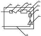
图1 为新型LED灯的结构示意图; Figure 1 is a schematic diagram of the structure of the new LED lamp;
图2 为印刷电路板的结构示意图; Fig. 2 is the structural representation of printed circuit board;
图3 为印刷电路板的LED驱动控制芯片结构示意图。 Figure 3 is a schematic diagram of the structure of the LED drive control chip on the printed circuit board.
具体实施方式 Detailed ways
以下结合附图和具体实施例,对本实用新型进行详细说明。 Below in conjunction with accompanying drawing and specific embodiment, the utility model is described in detail.
如图1 ,图 2,图3 所示,一种新型LED灯,包括灯壳1、LED单元22,LED单元22由至少一LED发光体2、印刷电路板3组成,印刷电路板3包括温度感应装置11、恒电流装置8、保险丝9、电源正负极线路4、6,保险丝9与印刷电路板3上的一条电源正极线路4相连接,线路温度超过预设温度时,自动熔断,恒电流装置8通过保险丝9与印刷电路板3的电源正负极线路4连接,温度感应装置11与印刷电路板3的电源正极线路4连接,用于监测温度,在超过预设温度时,自动切断电源;
As shown in Figure 1, Figure 2, and Figure 3, a new type of LED lamp includes a lamp housing 1 and an LED unit 22. The LED unit 22 is composed of at least one LED illuminant 2 and a printed
灯壳1后端设有LED单元22的驱动电源,灯壳1后端LED单元22的驱动电源线路与印刷电路板的电源正负极线路4、6相连接;
The rear end of the lamp housing 1 is provided with a driving power supply for the LED unit 22, and the driving power circuit of the LED unit 22 at the rear end of the lamp housing 1 is connected to the positive and
印刷电路板3上设有LED驱动控制芯片12、信号控制线路7,LED驱动控制芯片12通过信号控制线路7输入控制信号,驱动控制LED发光体2;
The printed
LED驱动控制芯片12包括LED驱动单元14、控制单元15、显示单元13,显示单元13、控制单元15、LED驱动单元14依次连接,LED驱动单元14根据显示单元13和控制单元15的输入信号驱动LED发光体2;
LED
LED发光体2为蓝色发光体、黄色发光体、红色发光体、白色发光体、紫色发光体; The LED illuminant 2 is a blue illuminant, a yellow illuminant, a red illuminant, a white illuminant, and a purple illuminant;
印刷电路板3设有金属散热基片5,金属散热基片5为铝片。
The printed
本实施例为实用新型的一种实施方式,但本实用新型并不局限于本实施例,任何基于本实施例的实施都属于本实用新型的保护范围。 This embodiment is an implementation of the utility model, but the utility model is not limited to this embodiment, and any implementation based on this embodiment belongs to the protection scope of the utility model. the
Claims (5)
Priority Applications (1)
| Application Number | Priority Date | Filing Date | Title |
|---|---|---|---|
| CN2012200053096U CN202494072U (en) | 2012-01-09 | 2012-01-09 | Novel LED lamp |
Applications Claiming Priority (1)
| Application Number | Priority Date | Filing Date | Title |
|---|---|---|---|
| CN2012200053096U CN202494072U (en) | 2012-01-09 | 2012-01-09 | Novel LED lamp |
Publications (1)
| Publication Number | Publication Date |
|---|---|
| CN202494072U true CN202494072U (en) | 2012-10-17 |
Family
ID=47000297
Family Applications (1)
| Application Number | Title | Priority Date | Filing Date |
|---|---|---|---|
| CN2012200053096U Expired - Fee Related CN202494072U (en) | 2012-01-09 | 2012-01-09 | Novel LED lamp |
Country Status (1)
| Country | Link |
|---|---|
| CN (1) | CN202494072U (en) |
-
2012
- 2012-01-09 CN CN2012200053096U patent/CN202494072U/en not_active Expired - Fee Related
Similar Documents
| Publication | Publication Date | Title |
|---|---|---|
| CN202494072U (en) | Novel LED lamp | |
| CN208901135U (en) | A kind of combination LED lamp | |
| CN204785777U (en) | Novel luminous LED lamp strip of high -power side | |
| CN201594360U (en) | Connection structure of flexible LED display | |
| CN203336366U (en) | Light source, backlight source and display device | |
| CN203297989U (en) | Disposable LED lamp | |
| CN201531764U (en) | LED lamp tube | |
| CN201589099U (en) | Plug-and-play high-brightness LED light-emitting plate structure | |
| CN216905384U (en) | Low-power consumption LED lamp and LED lamp subassembly | |
| CN219305075U (en) | Diffuse reflection LED lamp strip | |
| CN204554478U (en) | A LED luminous aluminum strip module | |
| CN204268164U (en) | Based on the safety-type LED module of FR-4 | |
| CN202532326U (en) | Dual-purpose light emitting diode (LED) lamp for park decoration and lighting | |
| CN203104953U (en) | LED (Light Emitting Diode) backlight flexible circuit board | |
| CN202546655U (en) | LED (light emitting diode) conduction module | |
| CN202493923U (en) | Intelligent LED lamp tube | |
| CN203177079U (en) | LED advertising lights | |
| CN2864344Y (en) | Inserted big power LED | |
| CN203590558U (en) | LED (light-emitting diode) car lamp module driving power supply | |
| CN203348980U (en) | High-power LED lamp module of chip on board | |
| CN202371580U (en) | LED (Light-Emitting Diode) energy-saving lamp applicable to delay switches of illuminating lamps in corridors | |
| CN202253471U (en) | AC LED tandem device | |
| CN209839769U (en) | Resistance-free low-voltage LED lamp strip | |
| CN202873149U (en) | Intelligent LED lamp dimming controller | |
| CN201774709U (en) | Control and drive circuit for semiconductor LED (light-emitting diode) meteor tube |
Legal Events
| Date | Code | Title | Description |
|---|---|---|---|
| C14 | Grant of patent or utility model | ||
| GR01 | Patent grant | ||
| EE01 | Entry into force of recordation of patent licensing contract |
Assignee: Shenzhen Allianz Photovoltaic System Engineering Co., Ltd. Assignor: Zhu Di Contract record no.: 2013440020143 Denomination of utility model: Novel light emitting diode lamp Granted publication date: 20121017 License type: Exclusive License Record date: 20130515 |
|
| LICC | Enforcement, change and cancellation of record of contracts on the licence for exploitation of a patent or utility model | ||
| C17 | Cessation of patent right | ||
| CF01 | Termination of patent right due to non-payment of annual fee |
Granted publication date: 20121017 Termination date: 20140109 |