CN202493801U - Hollow nail hole corrugated pipe - Google Patents
Hollow nail hole corrugated pipe Download PDFInfo
- Publication number
- CN202493801U CN202493801U CN2012200267979U CN201220026797U CN202493801U CN 202493801 U CN202493801 U CN 202493801U CN 2012200267979 U CN2012200267979 U CN 2012200267979U CN 201220026797 U CN201220026797 U CN 201220026797U CN 202493801 U CN202493801 U CN 202493801U
- Authority
- CN
- China
- Prior art keywords
- pipe
- corrugated pipe
- wall
- nonmetal
- hollow
- Prior art date
- Legal status (The legal status is an assumption and is not a legal conclusion. Google has not performed a legal analysis and makes no representation as to the accuracy of the status listed.)
- Expired - Fee Related
Links
- 229920003023 plastic Polymers 0.000 claims abstract description 22
- 239000004033 plastic Substances 0.000 claims abstract description 22
- 239000002184 metal Substances 0.000 claims abstract description 17
- 229910052755 nonmetal Inorganic materials 0.000 claims abstract description 16
- 239000002131 composite material Substances 0.000 claims description 4
- 238000002844 melting Methods 0.000 claims description 3
- 230000008018 melting Effects 0.000 claims description 3
- 238000000034 method Methods 0.000 abstract description 8
- 239000000463 material Substances 0.000 abstract description 5
- 238000007789 sealing Methods 0.000 abstract 1
- XLYOFNOQVPJJNP-UHFFFAOYSA-N water Substances O XLYOFNOQVPJJNP-UHFFFAOYSA-N 0.000 description 4
- 230000015572 biosynthetic process Effects 0.000 description 3
- 150000001875 compounds Chemical class 0.000 description 3
- 238000004519 manufacturing process Methods 0.000 description 3
- 230000007812 deficiency Effects 0.000 description 2
- 230000000694 effects Effects 0.000 description 2
- 230000004927 fusion Effects 0.000 description 2
- 239000002994 raw material Substances 0.000 description 2
- 230000010354 integration Effects 0.000 description 1
- 238000012986 modification Methods 0.000 description 1
- 230000004048 modification Effects 0.000 description 1
- 239000013502 plastic waste Substances 0.000 description 1
- 229920000098 polyolefin Polymers 0.000 description 1
- 238000013517 stratification Methods 0.000 description 1
Images

Landscapes
- Rigid Pipes And Flexible Pipes (AREA)
Abstract
The utility model relates to a hollow nail hole corrugated pipe which can effectively improve the strength of a large-caliber corrugated pipe, lighten the weight of the large-caliber corrugated pipe and reduce materials for making the large-caliber corrugated pipe. The wall of each hollow pipe core is distributed with a plurality of internal horn-shaped holes, the inner wall and the outer wall of each hollow pipe core are respectively compounded with a plastic layer, the hollow pipe cores with the plastic layers are spirally overlaid to form the corrugated pipe, and the spiral pipe walls forming the corrugated pipe are connected in a fused sealing manner. The hollow nail hole corrugated pipe has the advantages of opening up a precedent of the single-wall hollow nail hole corrugated pipe, improving the strength of the large-caliber corrugated pipe, lightening the weight of the large-caliber corrugated pipe and reducing the material consumption for making the large-caliber corrugated pipe; and because the metal pipe core or nonmetal pipe core walls is provided with the plurality of horn-shaped holes and the fused plastic layers on the metal pipe core walls or nonmetal pipe core walls are injected into the plurality of horn-shaped holes on the metal pipe core or nonmetal pipe core walls when being compounded in a fusing manner to form plastic rivet caps, and the plastic layers on the metal pipe core or nonmetal pipe core walls and the metal pipe cores or nonmetal pipe cores are firmly connected into a whole through the plastic rivet caps to ensure that no layering phenomenon can happen in the using process of the corrugated pipe.
Description
Technical field
The utility model relates to a kind ofly can improve heavy caliber bellows intensity effectively, can alleviate heavy caliber bellows weight again, can reduce a kind of SEMITUBULAR RIVET hole bellows of heavy caliber bellows material simultaneously again, belongs to bellows and makes the field.
Background technique
CN201731192U, title " large-caliber double-wall ripple water pipe ", its tube wall constitutes by the inside and outside is two-layer, and its inner tubal wall is smooth, and outer tube wall is trapezoidal corrugated, is provided with stirrup in the cavity between the inside and outside wall, and connects as one at outer wall trapezoidal bottom groove and inwall.Be provided with stirrup in the cavity between this large-caliber double-wall ripple water pipe inside and outside wall; Improved the intensity of water pipe; Compare with the large-diameter steel-plastic waste pipe that generally uses in the existing technology and to have that overall weight is light, cost is low, easy to install and characteristics that cost of production is low.Its deficiency: because the tube wall of bellows is made up of inner and outer wall, the compressive strength of its inwall strengthens through outer wall, and not only weight is big, and raw materials consumption is big, and compressive strength is uneven.
The model utility content
Purpose of design: avoid the deficiency in the background technique, design and a kind ofly can improve heavy caliber bellows intensity effectively, can alleviate heavy caliber bellows weight again, can reduce a kind of SEMITUBULAR RIVET hole bellows of heavy caliber bellows material simultaneously again.
Design proposal: in order to realize above-mentioned purpose of design.1, bellows is one of technical characteristics of the utility model the design that the plastic tube spiral that has the hollow tube core is formed by stacking.The purpose of doing like this is: it divides body structure with existing double-wall corrugated water pipe by bilayer; Change overall structure into, both escaped to eliminate the inwall in the background technique, integrated the outer wall in the background technique again; Make the ripple tube wall after the integration both have the function of inwall, have the function of outer wall again.Therefore, not only bearing strength is high, low cost of manufacture, and in light weight, greatly reduced raw-material consumption.2, have the design of a plurality of through holes and through hole flare on metal die or the nonmetal tube core face, be the utility model technical characteristics two.The purpose of doing like this is: because the through hole flare structure on metal die or the nonmetal tube core face; When molten plastic and the tubular skeleton compound tense of semicircle metal that is furnished with a plurality of tubaeform through holes; The plastics of its fusion externally effect of pressure get into down a plurality of inside trumpet shape through holes and formation and have nail and cover continuously connected fastener (ailhead), and this continuously connected fastener will be compounded in metal die or nonmetal tube core and metal die or nonmetal tube core and compound above that plastic layer firmly are connected as a single entity.
Technological scheme: a kind of SEMITUBULAR RIVET hole bellows; Be furnished with a plurality of inside trumpet shapes hole on the hollow tube core wall; Be furnished with a plurality of inside trumpet shapes hole on the hollow tube core wall; Composite plastic layer and the hollow tube core spiral that has a plastic layer are superimposed as bellows on the hollow tube in-core outer wall, constitute melting sealed connection between the volute wall of bellows.
The utility model is compared with background technique, and the one, started the precedent of single wall SEMITUBULAR RIVET hole bellows; The 2nd, both improved the intensity of heavy caliber bellows, alleviate heavy caliber bellows weight again, reduce the consumption of heavy caliber bellows material simultaneously again; The 3rd because have a plurality of flared hole on metal die or the nonmetal tube core wall and be positioned at metal die or nonmetal tube core wall on plastic layer at the fusion compound tense; Be injected into interior, the formation Plastic Rivets headkerchief of a plurality of flared hole on metal die or the nonmetal tube core wall; Plastic layer and metal die or nonmetal tube core wall that this Plastic Rivets headkerchief will be positioned on metal die or the nonmetal tube core wall firmly are connected as a single entity, and have guaranteed that bellows in use stratification can not take place.
Description of drawings
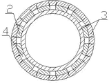
Fig. 1 is the structural representation of SEMITUBULAR RIVET hole bellows.
Fig. 2 is the sectional structure schematic representation of SEMITUBULAR RIVET hole bellows.
Embodiment
Embodiment 1: with reference to accompanying drawing 1.A kind of SEMITUBULAR RIVET hole bellows; Be furnished with a plurality of inside trumpet shapes hole on hollow tube core 2 walls; Composite plastic layer 3 and hollow tube core 2 spirals that have a plastic layer are superimposed as bellows 1 on hollow tube core 2 inside and outside walls, constitute melting sealed connection between the volute wall of bellows 1, and said hollow tube core 2 is metal die or nonmetal tube core; Its making method is an existing technology, is not described herein at this.Its making method: the heavy caliber polyolefin that hollow tube core 2 is made through the claimant twines and increases the directly distortion on bellow forming and the effect of two corrugated surfaces at bellow forming under in composite plastic layer 3 backs of pipe production line, overlaps, forms the bellows internal face, and has adhere formation SEMITUBULAR RIVET hole bellows outer wall between the plastic tube wall of hollow tube core 2.Be furnished with a plurality of inside trumpet shapes hole 4 on hollow tube core 2 walls.
What need understand is: the detailed text description though above-mentioned mentality of designing to the utility model is contrasted; But these text descriptions; Just the simple text of the utility model mentality of designing is described, rather than to the restriction of the utility model mentality of designing, any combination that does not exceed the utility model mentality of designing; Increase and modification, all fall in the protection domain of the utility model.
Claims (2)
1. SEMITUBULAR RIVET hole bellows; It is characterized in that: be furnished with a plurality of inside trumpet shapes hole on the hollow tube core wall; Composite plastic layer and the hollow tube core spiral that has a plastic layer are superimposed as bellows on the hollow tube in-core outer wall, constitute melting sealed connection between the volute wall of bellows.
2. SEMITUBULAR RIVET according to claim 1 hole bellows is characterized in that: said hollow tube core is metal die or nonmetal tube core.
Priority Applications (1)
| Application Number | Priority Date | Filing Date | Title |
|---|---|---|---|
| CN2012200267979U CN202493801U (en) | 2012-01-20 | 2012-01-20 | Hollow nail hole corrugated pipe |
Applications Claiming Priority (1)
| Application Number | Priority Date | Filing Date | Title |
|---|---|---|---|
| CN2012200267979U CN202493801U (en) | 2012-01-20 | 2012-01-20 | Hollow nail hole corrugated pipe |
Publications (1)
| Publication Number | Publication Date |
|---|---|
| CN202493801U true CN202493801U (en) | 2012-10-17 |
Family
ID=47000030
Family Applications (1)
| Application Number | Title | Priority Date | Filing Date |
|---|---|---|---|
| CN2012200267979U Expired - Fee Related CN202493801U (en) | 2012-01-20 | 2012-01-20 | Hollow nail hole corrugated pipe |
Country Status (1)
| Country | Link |
|---|---|
| CN (1) | CN202493801U (en) |
Cited By (1)
| Publication number | Priority date | Publication date | Assignee | Title |
|---|---|---|---|---|
| CN102705599A (en) * | 2012-01-20 | 2012-10-03 | 浙江双林机电科技有限公司 | Hollow tack hole corrugated pipe and manufacture method |
-
2012
- 2012-01-20 CN CN2012200267979U patent/CN202493801U/en not_active Expired - Fee Related
Cited By (1)
| Publication number | Priority date | Publication date | Assignee | Title |
|---|---|---|---|---|
| CN102705599A (en) * | 2012-01-20 | 2012-10-03 | 浙江双林机电科技有限公司 | Hollow tack hole corrugated pipe and manufacture method |
Similar Documents
| Publication | Publication Date | Title |
|---|---|---|
| CN201078523Y (en) | Heavy caliber framework tube polythene winding structure wall tube | |
| CN204554102U (en) | HDPE-PP composite winding reinforced pipe | |
| CN202493798U (en) | Hollow concave-convex corrugated pipe | |
| CN202493797U (en) | Hollow corrugated pipe | |
| CN202493802U (en) | Corrugated tube with hollow nailheads | |
| CN204004863U (en) | A kind of high pressure steel wire network framework polyethylene compound pipe | |
| CN102705596A (en) | Hollow corrugated pipe and manufacturing method thereof | |
| CN102705599B (en) | Hollow tack hole corrugated pipe and manufacture method | |
| CN202493796U (en) | Corrugated pipe formed by dovetail tenon groove pipes | |
| CN102705597B (en) | A kind of SEMITUBULAR RIVET head bellows and making method | |
| CN101649933A (en) | Enhanced plastic double-walled corrugated pipe and manufacturing method thereof | |
| CN104295815A (en) | Winding corrugated pipe and manufacturing method thereof | |
| CN207848641U (en) | A kind of ribbing winding Type B tubing | |
| CN102705604B (en) | Hollow concave-convex corrugated pipe and manufacture method thereof | |
| CN206988592U (en) | A kind of novel double-wall bellows | |
| CN202868125U (en) | D-shaped riveting helical bellow | |
| CN202834451U (en) | Large-caliber single-wall composite plastic-steel winding pipe | |
| CN102837454A (en) | High-gloss, low-friction three-layer co-extruded MPP pipe and production method thereof | |
| CN203476233U (en) | Drill rod joint with composite structure | |
| CN202862672U (en) | High-gloss, low-friction three-layer co-extruded MPP pipe | |
| CN202972239U (en) | Large-caliber framework pipe and pipe adopting large-caliber framework pipes and polyethylene winding structure wall | |
| CN206234496U (en) | One kind enhancing carat pipe | |
| CN202493792U (en) | Corrugated pipe consisting of internal composite plastic layer D-shaped framework | |
| CN207298120U (en) | A kind of novel alloy Type B winds corrugated pipe | |
| CN102705598A (en) | Corrugated pipe comprising dovetail tenon grooved pipes and manufacture method for corrugated pipe comprising dovetail tenon grooved pipes |
Legal Events
| Date | Code | Title | Description |
|---|---|---|---|
| C14 | Grant of patent or utility model | ||
| GR01 | Patent grant | ||
| CF01 | Termination of patent right due to non-payment of annual fee |
Granted publication date: 20121017 Termination date: 20190120 |
|
| CF01 | Termination of patent right due to non-payment of annual fee |