Reduction valve
Technical field:
The utility model relates to a kind of valving, specifically is a kind of reduction valve that is installed on the gas pipeline.
Background technique:
Reduction valve is a kind of valving that will get into its inner high pressure air reducing to a certain stabilizing low voltage gas.Generally all be provided with gas-entered passageway, outlet passageway and control channel on the valve body of existing reduction valve; The valve that is provided with between gas-entered passageway and the outlet passageway is used to control the break-make of gas-entered passageway and outlet passageway; The piston that is arranged between outlet passageway and the control channel is used for promoting valve so that valve is opened, and closing of valve then is to rely on to withstand on from the spring of body to realize, after valve is closed; Valve can be pressed on the seal face in the body cavity under the effect of spring force; In order to prevent gas leakage, seal washer generally all is housed on the valve seals, seal washer is processed by the polychlorotrifluoroethylene material usually.The reduction valve of this soft sealing structure of above-mentioned employing seal washer generally can only be used in the gas pipeline of inlet pressure less than 35MPa; If after being contained in it on gas pipeline that gas pressure is 45MPa; The pressure that seal washer bears is bigger; Very easily take place to wear out, thereby shorten the working life of reduction valve greatly.
The model utility content:
The technical problem that the utility model will solve is that it is on the 45MPa gas pipeline that a kind of gas pressure that not only can be applied in is provided, and working life is than long reduction valve.
The technical solution of the utility model is that a kind of reduction valve with following structure is provided: comprise valve body, piston, push rod, valve and first spring, valve body comprises following valve body, the suction flange that is connected down the upper valve body at valve body top and is connected the upper valve body top; Suction flange is provided with gas-entered passageway, and upper valve body is provided with the outlet passageway that communicates with gas-entered passageway, and following valve body is provided with control channel; Following valve body between control channel and the outlet passageway is provided with piston cavity, and piston can slide up and down on piston cavity top, and control channel communicates with the piston cavity bottom; Push rod one end is connected with valve, and the push rod the other end withstands on the piston, wherein; Also comprise the valve base and the gland that are positioned at gas-entered passageway, valve base is made up of chassis and the cylinder that is positioned at the top, chassis, and the chassis is provided with axial hole; Cylinder periphery wall bottom is provided with radial direction through hole, and the chassis is connected between suction flange and the upper valve body, and gland is connected the cylinder top; Valve is arranged in cylinder bore and its top can slide up and down at the gland inner chamber; First spring withstands between gland and the valve, and the valve lower end is provided with annular tip, and annular tip is pressed on the chassis of axial hole periphery.
The described reduction valve of the utility model wherein, is connected with safety valve on the upper valve body, the safety valve open top is used for communicating with control channel, and the bottom opening of safety valve communicates with outlet passageway.
After adopting above structure; Compared with prior art; The utility model reduction valve has the following advantages: that this soft seal of seal washer is installed on valve is different with the existing technology reduction valve; The valve lower end of the utility model reduction valve is provided with annular tip, and annular tip is pressed on the chassis of axial hole periphery, in other words; The utility model reduction valve adopt annular tip directly and the chassis be close to incompatible the sealing; Being sealed in that this metal and metal are directly fitted is referred to as hard sealing on the industry, the employing of hard sealing not only can make the utility model reduction valve be contained on the gas pipeline that gas pressure is 45MPa, and avoided seal washer because of the aging reduction valve problem in working life that shortens takes place.
Description of drawings:
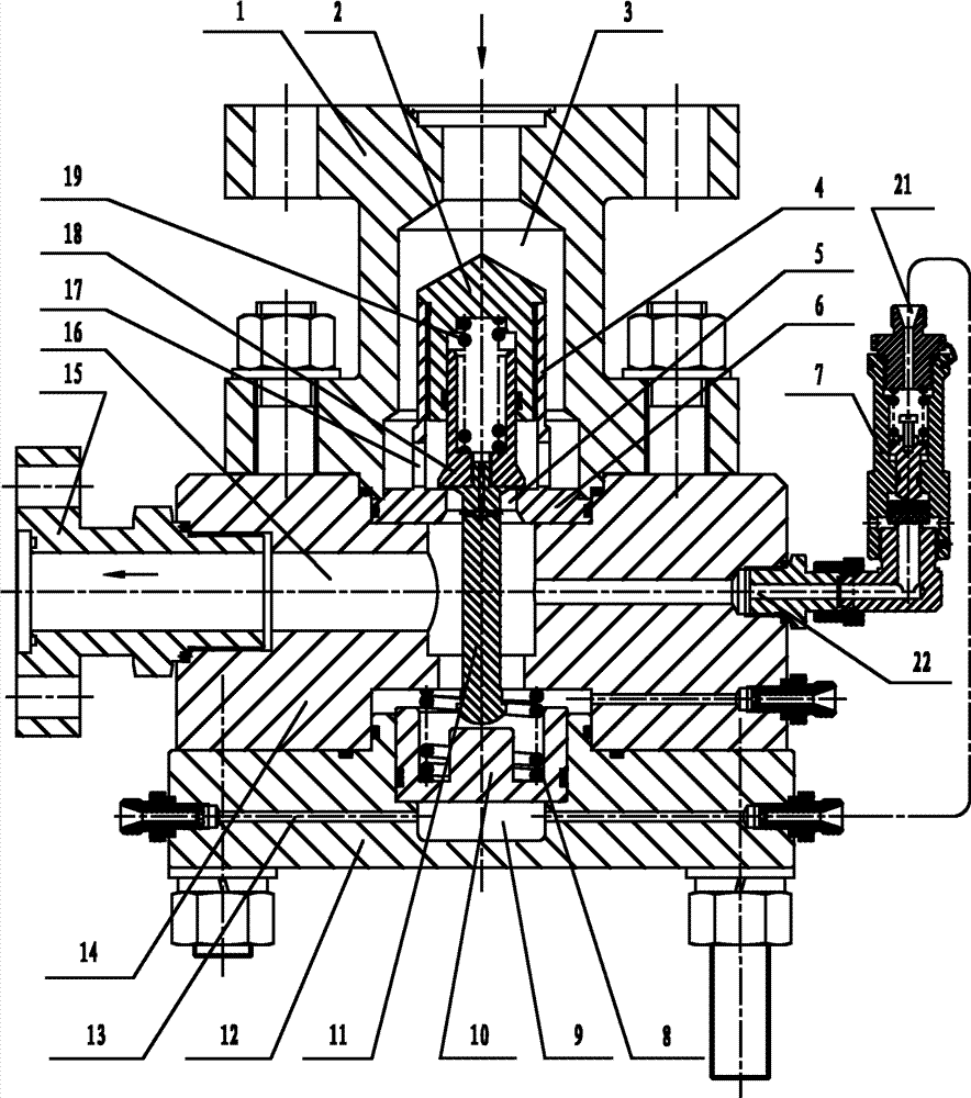
Fig. 1 is the sectional structure chart of the utility model reduction valve;
Fig. 2 is valve in the utility model reduction valve, first spring, gland, valve base and the push rod broken section amplification assumption diagram when linking together.
Embodiment:
Below in conjunction with accompanying drawing and embodiment the utility model reduction valve is done further explain:
As depicted in figs. 1 and 2, in this embodiment, the utility model reduction valve comprises valve body, piston 10, push rod 11, valve 18, first spring 19, gland 2 and valve base; Valve body comprises following valve body 12, is connected down the upper valve body 14 at valve body 12 tops and is connected the suction flange 1 at upper valve body 14 tops through bolt through bolt, and suction flange 1 is provided with gas-entered passageway 3, and upper valve body 14 is provided with the outlet passageway 16 that communicates with gas-entered passageway 3; Outlet passageway 16 left ends are connected with outlet(discharge) flange 15, are connected with safety valve 7 on the upper valve body 14, and safety valve 7 open tops 21 can communicate with control channel 13 through pipeline; The bottom opening 22 of safety valve 7 communicates with outlet passageway 16, and following valve body 12 is provided with control channel 13, and the following valve body 12 between control channel 13 and the outlet passageway 16 is provided with piston cavity 9; Piston 10 can slide up and down on piston cavity 9 tops, is provided with second spring, 8, the second springs 8 between piston 10 and the upper valve body 14 and withstands between piston 10 and the upper valve body 14; Control channel 13 communicates with piston cavity 9 bottoms, and push rod 11 upper ends are connected with valve 18, and push rod 11 lower ends withstand on the piston 10; Valve base and gland 2 all are positioned at gas-entered passageway 3; Valve base is made up of chassis 6 and the cylinder 4 that is positioned at 6 tops, chassis, and chassis 6 is provided with axial hole 5, and cylinder 4 periphery wall bottoms are provided with radial direction through hole 17; Chassis 6 is connected between suction flange 1 and the upper valve body 14; Gland 2 is connected cylinder 4 tops, and valve 18 is arranged in cylinder 4 inner chambers and valve 18 tops can slide up and down at gland 2 inner chambers, and first spring 19 withstands between gland 2 and the valve 18; Valve 18 lower ends are provided with annular tip 20 (see figure 2)s, and annular tip 20 is pressed on the chassis 6 of axial hole 5 peripheries.In this embodiment, described safety valve 7 is conventional existing technology, so no longer this gives unnecessary details.
The working principle of the utility model reduction valve is: during use, gas-entered passageway 3 is connected with the pressurized gas pipeline (not shown) of 45MPa, and outlet passageway 16 is connected with post-decompression low-pressure gas pipeline (not shown); At this moment, valve 18 is being close under the effect of first spring 19 and 45MPa pressurized gas on the chassis 6 of valve base, at this moment; Gas-entered passageway 3 breaks off with outlet passageway 16, and no pressure in the outlet passageway 16 is after control channel 13 and external control source of the gas (not shown) are connected; Move upward under the control gaseous pressure effect of piston 10 in control channel 13; Promote push rod 11, push rod 11 promotes valve 18 again, just forms a narrow slit between valve 18 and the chassis 6; The pressurized gas of 45Mpa receive throttling when passing through this slit, pressure reduces and flows out from outlet passageway 16.Regulate the pressure of control channel 13 inner control gases; Just can governor valve 18 height opened; Slit between valve 18 and the chassis 6 will increase thereupon, and the pressure in the outlet passageway 16 also and then increases, when the gas in the outlet passageway 16 reaches the force value of setting; Closing control passage 13, the utility model reduction valve just can infeed the pressed gas of setting value continuously in outlet passageway 16.In this process, when reducing, the gas pressures in the outlet passageway 16 also and then reduce piston 10 downward active forces because of reason in certain (like the decline of the pressure in the gas-entered passageway 3) when the gas pressure in the outlet passageway 16; Piston 10 will be reserved in control channel 13 under the pressure effect of gas and move upward, and with valve 18 top De Gengkai, the slit between valve 18 and the chassis 6 is bigger through push rod 11; At this moment, the gas pressure in the outlet passageway 16 returns to original gas pressure setting value again, otherwise; When the gas pressure in the outlet passageway 16 raises; Valve 18 moves downward under the effect of first spring, 19 reposition forces, and the slit reduces, therefore; Slit between valve 18 and the chassis 6 always is in a kind of dynamic equilibrium state, has guaranteed that the gas pressure in the outlet passageway 16 is stable.
Above-described embodiment describes the preferred implementation of the utility model; Be not that scope to the utility model limits; Under the prerequisite that does not break away from the utility model design spirit; Various distortion and improvement that those of ordinary skills make the technological scheme of the utility model all should fall in the definite protection domain of the utility model claims.