CN202493725U - Electric heating faucet with anti-freeze pressure releasing device - Google Patents
Electric heating faucet with anti-freeze pressure releasing device Download PDFInfo
- Publication number
- CN202493725U CN202493725U CN2012200936130U CN201220093613U CN202493725U CN 202493725 U CN202493725 U CN 202493725U CN 2012200936130 U CN2012200936130 U CN 2012200936130U CN 201220093613 U CN201220093613 U CN 201220093613U CN 202493725 U CN202493725 U CN 202493725U
- Authority
- CN
- China
- Prior art keywords
- cavity
- silica gel
- pressure
- container
- holddown spring
- Prior art date
- Legal status (The legal status is an assumption and is not a legal conclusion. Google has not performed a legal analysis and makes no representation as to the accuracy of the status listed.)
- Expired - Fee Related
Links
- 230000002528 anti-freeze Effects 0.000 title claims abstract description 22
- 238000005485 electric heating Methods 0.000 title abstract description 9
- 108010053481 Antifreeze Proteins Proteins 0.000 title abstract 3
- VYPSYNLAJGMNEJ-UHFFFAOYSA-N Silicium dioxide Chemical compound O=[Si]=O VYPSYNLAJGMNEJ-UHFFFAOYSA-N 0.000 claims abstract description 36
- 239000000741 silica gel Substances 0.000 claims abstract description 36
- 229910002027 silica gel Inorganic materials 0.000 claims abstract description 36
- 238000010438 heat treatment Methods 0.000 claims abstract description 30
- XLYOFNOQVPJJNP-UHFFFAOYSA-N water Substances O XLYOFNOQVPJJNP-UHFFFAOYSA-N 0.000 claims description 69
- 239000012528 membrane Substances 0.000 claims description 13
- 229910052573 porcelain Inorganic materials 0.000 claims description 6
- 230000000149 penetrating effect Effects 0.000 abstract 2
- 238000007710 freezing Methods 0.000 description 23
- 230000008014 freezing Effects 0.000 description 22
- 230000009172 bursting Effects 0.000 description 2
- 238000005516 engineering process Methods 0.000 description 2
- 238000009413 insulation Methods 0.000 description 2
- 208000027418 Wounds and injury Diseases 0.000 description 1
- 230000002159 abnormal effect Effects 0.000 description 1
- 239000000853 adhesive Substances 0.000 description 1
- 230000001070 adhesive effect Effects 0.000 description 1
- 230000006378 damage Effects 0.000 description 1
- 230000000694 effects Effects 0.000 description 1
- 239000003292 glue Substances 0.000 description 1
- 239000008236 heating water Substances 0.000 description 1
- 208000014674 injury Diseases 0.000 description 1
- 238000000034 method Methods 0.000 description 1
- 238000012856 packing Methods 0.000 description 1
- 238000007789 sealing Methods 0.000 description 1
Images


Landscapes
- Heat-Pump Type And Storage Water Heaters (AREA)
Abstract
The invention discloses an electric heating faucet with an anti-freeze pressure releasing device. The electric heating faucet with the anti-freeze pressure releasing device comprises an electric heating faucet container. A pressure chamber and a heating chamber are arranged in the electric heating faucet container. A container end cover is arranged at the lower end of the heating chamber. A protruding block is arranged on the container end cover. A protruding block cavity penetrates through the protruding block from top to bottom. The inner side wall of the protruding block cavity is provided with at least one gutter. A pressure release outlet is arranged at the upper end of the protruding block cavity. A silica gel stopple, a pressure spring and a pressure spring fixing piece are arranged in the protruding block cavity from top to bottom in sequence. An end cap matched with the protruding block cavity is arranged at the lower end of the silica gel stopple. A silica gel stopple cavity is arranged in the silica gel stopple. An end cap cavity penetrating through the end cap from up to bottom is arranged in the end cap. The end cap cavity is communicated with the silica gel stopple cavity in penetrating mode. The pressure spring fixing piece is arranged at the bottom of the container end cover. Pressure release holes are arranged on the pressure spring fixing piece. The pressure spring is arranged in the end cap cavity. The upper end of the pressure spring abuts the top of the end cap cavity. The lower end of the pressure spring abuts the pressure spring fixing piece. A cavity opening and closing end cap is arranged at the lower end of films.
Description
Technical field
The utility model relates to a kind of electric hot water tap that antifreeze pressure relief device is housed.
Background technique
Electric hot water tap is a kind of at a non-heat insulation or heat insulation slightly vessel in heating water; Generally be meant when cold water flows through heater an electric heating appliance of the uniform temperature that the temperature of leaning on the electric heating tube heating to make water improves fast, this utensil is that to lean on water pressure switch to start be the heated chamber of a water outlet open type.Electric hot water tap ownership quick-heating type electric water heater; Must satisfy the standard-required of GB4706.1-2005 (the general requirement of family expenses and similar applications electrical equipment), GB4706.11-2008 (specific (special) requirements of quick-heating type electric water heater) simultaneously; Standard 22.109 (water container that has the open-type water heater of pressure switch would not break owing to internal pressure is too high) wherein; Existing in the market electric hot water tap does not all have this pressure release and anti-freezing device, so this product reaches non-normal working under freezing state (refer to that water outlet stops up and water freezing in the container, volumetric expansion 10% during water freezing; And the water in the pressure switch when expanding volume increase can be glued membrane jack-up and energized; And the water freezing in the heating chamber, the heating pipe heating, ice can be vaporized; And the thermal fuse-link of this machine configuration itself is because freezing reason has little time action; Electric heating tube heating will have been burnt machine like this) burning and blast can take place down in state, and this understands bring personal injury or property loss to the Consumer, has very big potential safety hazard.
The model utility content
The technical problem that the utility model will solve provides a kind of electric hot water tap that antifreeze pressure relief device is housed that can under abnormal operating state, work.
In order to solve the problems of the technologies described above, the utility model provides a kind of electric hot water tap that antifreeze pressure relief device is housed, and comprises the electric hot water tap container; Be provided with pressure chamber and heating chamber in the said electric hot water tap container; Said pressure chamber upper end is provided with glued membrane, is provided with the porcelain nail in the upper end of glued membrane, and the porcelain side of nailing on is provided with moving/fixed contact; Be provided with heating pipe in the said heating chamber, said heating chamber lower end is provided with container end; Said container end is provided with the projection piece; Be provided with the projection piece cavity of up/down perforation in the said projection piece, said projection piece cavity madial wall is provided with at least one gutter, and said projection piece cavity upper end is provided with pressure relief opening; In said projection piece cavity, be disposed with silica gel stopple, holddown spring and holddown spring fixed plate from top to bottom; Said silica gel stopple lower end is provided with the plug that matches with projection piece cavity, is provided with silica gel stopple cavity in the said silica gel stopple, is provided with the plug cavity that runs through up and down in the said plug, and said plug cavity runs through with silica gel stopple cavity and is communicated with; The bottom of said container end is provided with the holddown spring fixed plate; Said holddown spring fixed plate is provided with relief hole; Be provided with holddown spring in the said plug cavity, the upper end of said holddown spring props up the top of plug cavity, and the lower end of said tight spring props up the holddown spring fixed plate; The bottom of said pressure chamber is provided with the switch cavity plug.
As the improvement to the electric hot water tap that antifreeze pressure relief device is housed of the utility model: said holddown spring fixed plate lower end is provided with the PVC trim.
When the electric hot water tap that antifreeze pressure relief device is housed of the utility model reached non-normal working under freezing state, when the pressure in the heating chamber surpassed 1.1Mpa, the hydraulic pressure in the heating chamber will back down the silica gel stopple; Holddown spring begins to shrink; Plug no longer withstands pressure relief opening, and the water of this moment can arrive the holddown spring fixed plate under the guiding of gutter 15; Flow out (at this moment, the PVC trim just drops after receiving the pressure of water) by relief hole again; When the inside of silica gel stopple is hollow, can't move as freezing the jail when the silica gel stopple, can compress the silica gel stopple when pressure in the heating chamber is excessive, the purpose that the volume of silica gel stopple reduces also can reach pressure release like this is to prevent that container is by bursting by freezing; The inner wall sealing of the pressure chamber that starts when silica gel stopple and hydraulic pressure; The volumetric expansion of icing in the pressure chamber when loading onto a plug that reduces the pressure switch cavity volume and can guarantee water freezing can not connected circuit (because glued membrane needs certain pressure will start the time; And reduce the volume of water; When freezing, do not reach the pressure of machine startup because water is few, just can not be glued membrane jack-up and energized).
Have the electric hot water tap of the antifreeze pressure relief device of double insurance through this device, when guaranteeing that pressure surpasses 1.1Mpa, can releasing pressure automatically and keep the electric hot water tap no electric circuit of antifreeze pressure relief device.
Description of drawings
Below in conjunction with accompanying drawing the embodiment of the utility model is done further explain.
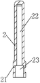
Fig. 1 is the electric hot water tap main structure schematic representation that antifreeze pressure relief device is housed of the utility model;
Structure for amplifying schematic representation when Fig. 2 is container end 1 among Fig. 1, silica gel stopple 2, holddown spring 3, holddown spring fixed plate 4 and 5 assemblings of PVC trim:
Fig. 3 is the structure for amplifying schematic representation of container end 1 among Fig. 1:
Fig. 4 is the structure for amplifying schematic representation of silica gel stopple 2 among Fig. 1.
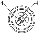
Fig. 5 is the structure for amplifying schematic representation of holddown spring fixed plate 4 among Fig. 1.
Embodiment
The outer side wall of electric hot water tap container 6 lower ends is provided with the electric hot water tap screw thread, is provided with the container end cavity 11 of no ceiling in the container end 1, on the madial wall of container end cavity 11, establishes the container end screw thread that matches with the electric hot water tap screw thread; Be provided with columniform projection piece 12 at container end cavity 11 bottom surfaces; In projection piece 12, be provided with the projection piece cavity 13 of up/down perforation; Projection piece cavity 13 madial walls are provided with gutter 15 (gutter 15 from the tops of projection piece cavity 13 madial walls until projection piece cavity 13 madial walls bottom), are provided with pressure relief opening 14 in the upper end of projection piece cavity 13.
Concrete is that silica gel stopple 2 is inserted from projection piece cavity 13 lower ends, blocks pressure relief opening 14 fully up to plug 21; In plug cavity 23, overlap the holddown spring 3 of packing into; Holddown spring fixed plate 4 is fixed on the lower end of projection piece cavity 13 in the lower end of holddown spring 3; Use glue to be adhesive with PVC trim 5 (PVC trim 5 is only done to decorate and is used in the lower end of holddown spring fixed plate 4; Under the pressure of water, promptly can drop).
The bottom of pressure chamber 60 is provided with switch cavity plug 65; Switch cavity plug 65 is used to reduce the volume of water in the pressure chamber 60, with prevent water when freezing volumetric expansion and cause energized (because water is when freezing, volume can expand about 10%; And the amount of the water in the minimizing pressure chamber 60; Can reduce total volume that water increases when freezing, to reach water when freezing, total volume is not enough to the purpose of jack-up glued membrane 63 in the pressure chamber 60).
The utility model the electric hot water tap real work of antifreeze pressure relief device is housed the time, main antifreeze blowdown step is (the water heating process of electric hot water tap that antifreeze pressure relief device is housed is identical with existing electric hot water tap) as follows:
The electric hot water tap that antifreeze pressure relief device is housed under freezing state and non-normal working (be that water outlet stops up and water freezing in the container; Volumetric expansion 10% during water freezing; And the water of 60 li of pressure chambers that hydraulic pressure starts when expanding volume increase can be glued membrane 63 jack-up and energized, and the water freezing in the heating chamber, heating pipe heating; Ice can be vaporized; And the thermal fuse-link of this machine configuration itself is because freezing reason has little time action, and electric heating tube heats and will burn machine like this) time, the electric hot water tap of the antifreeze pressure relief device of the utility model have following several aspects effect:
1, when the pressure of 62 li of heating chambers surpasses 1.1Mpa; The hydraulic pressure that heating chamber is 62 li will back down silica gel stopple 2, and holddown spring 3 begins to shrink, and plug 21 no longer withstands pressure relief opening 14; The water of this moment can be under the guiding of gutter 15; Arrive holddown spring fixed plate 4, flow out (at this moment, PVC trim 5 just drops after receiving the pressure of water) by relief hole 41 again.
2, the inside of silica gel stopple 2 is hollow, can't move as freezing the jail when silica gel stopple 2, can compress silica gel stopple 2 when the pressure that heating chamber is 62 li is excessive, and the purpose that the volume of silica gel stopple 2 reduces also can reach pressure release like this is to prevent that container is by bursting by freezing.
3, silica gel stopple 2 seals with the madial wall of pressure chamber 60; Load onto a switch cavity plug 65 that reduces the pressure switch cavity volume; The volumetric expansion of 60 li ice of pressure chamber can not connected circuit and (needed certain pressure in the time of will starting because of glued membrane 63, and reduce the volume of water, when water freezes in the time of guaranteeing water freezing; Do not reach the pressure of machine startup because water is few, just can not be glued membrane 63 jack-up and energized).
Have the electric hot water tap of the antifreeze pressure relief device of double insurance through this device, when guaranteeing that pressure surpasses 1.1Mpa, can releasing pressure automatically and keep the electric hot water tap no electric circuit of antifreeze pressure relief device.
At last, it is also to be noted that what more than enumerate only is a specific embodiment of the present invention.Obviously, the invention is not restricted to above embodiment, many distortion can also be arranged.All distortion that those of ordinary skill in the art can directly derive or associate from content disclosed by the invention all should be thought protection scope of the present invention.
Claims (2)
1. the electric hot water tap of antifreeze pressure relief device is housed, comprises electric hot water tap container (6); Be provided with pressure chamber (60) and heating chamber (62) in the said electric hot water tap container (6); Said pressure chamber (60) upper end is provided with glued membrane (63), is provided with the porcelain nail in the upper end of glued membrane (63), and the porcelain side of nailing on is provided with moving/fixed contact; Be provided with heating pipe (64) in the said heating chamber (62), said heating chamber (62) lower end is provided with container end (1); It is characterized in that: said container end (1) is provided with projection piece (12); Be provided with the projection piece cavity (13) of up/down perforation in the said projection piece (12), said projection piece cavity (13) madial wall is provided with at least one gutter (15), and said projection piece cavity (13) upper end is provided with pressure relief opening (14);
In said projection piece cavity (13), be disposed with silica gel stopple (2), holddown spring (3) and holddown spring fixed plate (4) from top to bottom;
Said silica gel stopple (2) lower end is provided with the plug (21) that matches with projection piece cavity (13); Be provided with silica gel stopple cavity (22) in the said silica gel stopple (2); Be provided with the plug cavity (23) that runs through up and down in the said plug (21), said plug cavity (23) runs through with silica gel stopple cavity (22) and is communicated with;
The bottom of said container end (1) is provided with holddown spring fixed plate (4); Said holddown spring fixed plate (4) is provided with relief hole (41); Be provided with holddown spring (3) in the said plug cavity (23); The upper end of said holddown spring (3) props up the top of plug cavity (23), and the lower end of said tight spring (3) props up holddown spring fixed plate (4);
The bottom of said pressure chamber (60) is provided with switch cavity plug (62).
2. the electric hot water tap that antifreeze pressure relief device is housed according to claim 1 is characterized in that: said holddown spring fixed plate (4) lower end is provided with PVC trim (5).
Priority Applications (1)
| Application Number | Priority Date | Filing Date | Title |
|---|---|---|---|
| CN2012200936130U CN202493725U (en) | 2012-03-13 | 2012-03-13 | Electric heating faucet with anti-freeze pressure releasing device |
Applications Claiming Priority (1)
| Application Number | Priority Date | Filing Date | Title |
|---|---|---|---|
| CN2012200936130U CN202493725U (en) | 2012-03-13 | 2012-03-13 | Electric heating faucet with anti-freeze pressure releasing device |
Publications (1)
| Publication Number | Publication Date |
|---|---|
| CN202493725U true CN202493725U (en) | 2012-10-17 |
Family
ID=46999957
Family Applications (1)
| Application Number | Title | Priority Date | Filing Date |
|---|---|---|---|
| CN2012200936130U Expired - Fee Related CN202493725U (en) | 2012-03-13 | 2012-03-13 | Electric heating faucet with anti-freeze pressure releasing device |
Country Status (1)
| Country | Link |
|---|---|
| CN (1) | CN202493725U (en) |
Cited By (1)
| Publication number | Priority date | Publication date | Assignee | Title |
|---|---|---|---|---|
| CN103542156A (en) * | 2013-09-30 | 2014-01-29 | 安徽华印机电股份有限公司 | Anti-freezing faucet |
-
2012
- 2012-03-13 CN CN2012200936130U patent/CN202493725U/en not_active Expired - Fee Related
Cited By (1)
| Publication number | Priority date | Publication date | Assignee | Title |
|---|---|---|---|---|
| CN103542156A (en) * | 2013-09-30 | 2014-01-29 | 安徽华印机电股份有限公司 | Anti-freezing faucet |
Similar Documents
| Publication | Publication Date | Title |
|---|---|---|
| CN105498145A (en) | Fire-fighting spraying device capable of being manually and automatically controlled | |
| EP4485659A1 (en) | Battery explosion-proof valve, battery plug-in box and electric apparatus | |
| CN204932689U (en) | Constant temperature starts hanged extinguishing equipment with electricity | |
| CN202493725U (en) | Electric heating faucet with anti-freeze pressure releasing device | |
| US10190800B2 (en) | Heatable fluid bag | |
| CN106618204A (en) | One-time heating heat-insulating water dispenser equipment | |
| CN101761675A (en) | Novel safety valve for water heater | |
| CN202901413U (en) | Explosion-proof device of electric heating faucet | |
| CN111013053B (en) | Oil-immersed transformer fire-fighting cabinet capable of recycling oil | |
| CN203447116U (en) | Automatic power-off water heater | |
| CN209019842U (en) | Impacting type temperature sensing glass ball starter | |
| CN201992189U (en) | Automatic heating and starting structure of electric heating water faucet | |
| CN203384477U (en) | Electric heating faucet | |
| CN201028113Y (en) | Intelligent porcelain wave water tap | |
| CN106028482A (en) | Multiple protection quartz capsule heating device | |
| CN203777138U (en) | Automatic breathable explosion-proof electric hot-water bag | |
| CN202792497U (en) | Normal pressure water storage water heater | |
| CN207408322U (en) | A kind of cement boils case | |
| CN204932688U (en) | Constant temperature and electric detonation start hanged extinguishing equipment | |
| CN102734918A (en) | An electric water heater capable of preventing dry heating of heat pipes and power failure due to low water pressure | |
| CN201322363Y (en) | Closed loop circulating electric heater with pressure relief device | |
| CN202510786U (en) | Dual depressurization protective device of quick-heating water faucet | |
| CN104214385B (en) | Gas safety valve | |
| CN207950373U (en) | A kind of non-stored-pressure type dry powder extinguishing installation based on heat-actuated means | |
| CN102537508B (en) | Double decompression protection device for quick hot water faucet |
Legal Events
| Date | Code | Title | Description |
|---|---|---|---|
| C14 | Grant of patent or utility model | ||
| GR01 | Patent grant | ||
| CF01 | Termination of patent right due to non-payment of annual fee | ||
| CF01 | Termination of patent right due to non-payment of annual fee |
Granted publication date: 20121017 Termination date: 20210313 |