CN202493660U - Planet speed reducer with foot margins symmetrically arranged top and bottom - Google Patents
Planet speed reducer with foot margins symmetrically arranged top and bottom Download PDFInfo
- Publication number
- CN202493660U CN202493660U CN2012200148170U CN201220014817U CN202493660U CN 202493660 U CN202493660 U CN 202493660U CN 2012200148170 U CN2012200148170 U CN 2012200148170U CN 201220014817 U CN201220014817 U CN 201220014817U CN 202493660 U CN202493660 U CN 202493660U
- Authority
- CN
- China
- Prior art keywords
- box body
- upper box
- symmetrically arranged
- speed reducer
- box
- Prior art date
- Legal status (The legal status is an assumption and is not a legal conclusion. Google has not performed a legal analysis and makes no representation as to the accuracy of the status listed.)
- Expired - Fee Related
Links
- 239000003638 chemical reducing agent Substances 0.000 title claims abstract description 17
- 238000009434 installation Methods 0.000 abstract description 3
- 238000005516 engineering process Methods 0.000 description 2
- 230000009286 beneficial effect Effects 0.000 description 1
- 230000015572 biosynthetic process Effects 0.000 description 1
- 230000007812 deficiency Effects 0.000 description 1
- 239000012467 final product Substances 0.000 description 1
- 238000000034 method Methods 0.000 description 1
Images

Landscapes
- Framework For Endless Conveyors (AREA)
Abstract
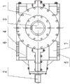
The utility model relates to a planet speed reducer with foot margins symmetrically arranged top and bottom, in particular to a speed reducer arranged a belt-type conveyer, belonging to the technical field of speed reducers and aiming at solving the technical problem of providing the planet speed reducer which can be suitable for two installation directions and is provided with the foot margins symmetrically arranged top and bottom. The planet speed reducer with the foot margins symmetrically arranged top and bottom comprises a box body, a first extending shaft and a second extending shaft, wherein the box body comprises an upper box body and a lower box body, the upper box body and the lower box body are together connected through bolts; the first extending shaft extends out of a connecting surface of the upper box body and the lower box body, and the second extending shaft extends out of the other connecting surface of the upper box body and the lower box body; the upper box body and the lower box body are structurally symmetrical; the upper box body is provided with a plurality of first foot margin connection holes, and the lower box body is provided with a plurality of second foot margin connection holes; and the first foot margin connection holes and the second foot margin connection holes are symmetrically arranged. The speed reducer is mainly used for the belt-type conveyer.
Description
Technical field
A kind of lower margin of the utility model is symmetrically arranged planetary reducer up and down, belongs to the retarder technical field, is specifically related to a kind of retarder that is installed on the Belt Conveyors.
Background technique
At present; The band lower margin planetary reducer of using can only be applicable to a kind of installation direction; And great majority are two retarder symmetric arrangement on the Belt Conveyors, need the retarder of two assembling pattern symmetries, so just need produce retarder according to the symmetrical pattern of two covers; Also want two cover acknowledgment copies, produce assembling inconvenience.
The model utility content
The utility model overcomes the deficiency that existing technology exists, and technical problem to be solved provides a kind of lower margin that can be applicable to two kinds of installation directions symmetrically arranged planetary reducer up and down.
In order to solve the problems of the technologies described above, the technological scheme that the utility model adopts is: a kind of lower margin is symmetrically arranged planetary reducer up and down, comprises casing, first projecting shaft and second projecting shaft; Casing comprises upper box and lower box; Upper box and lower box link together through bolt, and first projecting shaft stretches out from a junction surface of upper box and lower box, and second projecting shaft stretches out from another junction surface of upper box and lower box; Upper box and lower box symmetrical configuration; Have a plurality of first lower margin attachment holes on the upper box, have a plurality of second lower margin attachment holes on the lower box, the first lower margin attachment hole and the second lower margin attachment hole are for being symmetrical set.
Described first projecting shaft and second projecting shaft form the right angle.
The beneficial effect that the utility model is compared with prior art had is: on upper box and lower box, be symmetrical set the lower margin attachment hole, the utility model can be fixed by both direction, the acknowledgment copy cost reduces, and tissue is produced and used also convenient.
Description of drawings
Below in conjunction with accompanying drawing symmetrically arranged planetary reducer about a kind of lower margin of the utility model is described further.
Fig. 1 is a kind of lower margin of the utility model structural representation of symmetrically arranged planetary reducer up and down.
Fig. 2 is the left view of Fig. 1.
Among the figure: 1 is casing, and 2 is first projecting shaft, and 3 is second projecting shaft, and 4 is the first lower margin attachment hole, and 5 is the second lower margin attachment hole, and 6 is upper box, and 7 is lower box.
Embodiment
Like Fig. 1, a kind of lower margin shown in Figure 2 symmetrically arranged planetary reducer up and down; Comprise casing 1, first projecting shaft 2 and second projecting shaft 3, casing 1 comprises upper box 6 and lower box 7, and upper box 6 and lower box 7 link together through bolt; First projecting shaft 2 stretches out from a junction surface of upper box 6 and lower box 7; Second projecting shaft 3 stretches out from another junction surface of upper box 6 and lower box 7, it is characterized in that: upper box 6 and lower box 7 symmetrical configuration have a plurality of first lower margin attachment holes 4 on the upper box 6; Have a plurality of second lower margin attachment hole, 5, the first lower margin attachment holes 4 and the second lower margin attachment hole 5 on the lower box 7 for being symmetrical set.
Described first projecting shaft 2 and second projecting shaft, 3 formation right angles.
The utility model is because the first lower margin attachment hole 4 and the second lower margin attachment hole 5 are for being symmetrical set; Therefore; When the utility model is installed on Belt Conveyors, a side of the first lower margin attachment hole 4 on the upper box 6 and Belt Conveyors with bolt, is got final product the opposite side of the second lower margin attachment hole 5 on the lower box 7 with Belt Conveyors with bolt; Only need the utility model of a kind of model, not only reduced cost but also made things convenient for the production assembling.
Claims (2)
1. a lower margin symmetrically arranged planetary reducer up and down; Comprise casing (1), first projecting shaft (2) and second projecting shaft (3); Casing (1) comprises upper box (6) and lower box (7); Upper box (6) links together through bolt with lower box (7), and first projecting shaft (2) stretches out from a junction surface of upper box (6) and lower box (7), and second projecting shaft (3) stretches out from another junction surface of upper box (6) and lower box (7); It is characterized in that: upper box (6) and lower box (7) symmetrical configuration; Have a plurality of first lower margin attachment holes (4) on the upper box (6), have a plurality of second lower margin attachment holes (5) on the lower box (7), the first lower margin attachment hole (4) and the second lower margin attachment hole (5) are for being symmetrical set.
2. according to requirement 1 described a kind of lower margin symmetrically arranged planetary reducer up and down of having the right, it is characterized in that: described first projecting shaft (2) forms the right angle with second projecting shaft (3).
Priority Applications (1)
| Application Number | Priority Date | Filing Date | Title |
|---|---|---|---|
| CN2012200148170U CN202493660U (en) | 2012-01-13 | 2012-01-13 | Planet speed reducer with foot margins symmetrically arranged top and bottom |
Applications Claiming Priority (1)
| Application Number | Priority Date | Filing Date | Title |
|---|---|---|---|
| CN2012200148170U CN202493660U (en) | 2012-01-13 | 2012-01-13 | Planet speed reducer with foot margins symmetrically arranged top and bottom |
Publications (1)
| Publication Number | Publication Date |
|---|---|
| CN202493660U true CN202493660U (en) | 2012-10-17 |
Family
ID=46999892
Family Applications (1)
| Application Number | Title | Priority Date | Filing Date |
|---|---|---|---|
| CN2012200148170U Expired - Fee Related CN202493660U (en) | 2012-01-13 | 2012-01-13 | Planet speed reducer with foot margins symmetrically arranged top and bottom |
Country Status (1)
| Country | Link |
|---|---|
| CN (1) | CN202493660U (en) |
-
2012
- 2012-01-13 CN CN2012200148170U patent/CN202493660U/en not_active Expired - Fee Related
Similar Documents
| Publication | Publication Date | Title |
|---|---|---|
| CN202493660U (en) | Planet speed reducer with foot margins symmetrically arranged top and bottom | |
| CN201458265U (en) | Large-inclination chain type scraper coal feeder | |
| CN202810922U (en) | Ramp pan and scraper conveyor | |
| CN201694608U (en) | E-shaped bolt of scraper conveyor | |
| CN204441268U (en) | Silicon chip separating mechanism | |
| CN203372717U (en) | Plane swerving device of belt conveyor | |
| CN204361611U (en) | A kind of vertical crane span structure seven word fastener | |
| CN201343297Y (en) | Supporting roller for curve segment of belt conveyor | |
| CN201686283U (en) | Middle groove and scraper conveyer | |
| CN202851572U (en) | Oil way bolt | |
| CN205802194U (en) | A kind of ribbon conveyer frame connecting structure | |
| CN202296146U (en) | Chain structure used for stable operation of conveying chain | |
| CN203099297U (en) | Deformed cross-section profile steel | |
| CN203051682U (en) | Gear ring | |
| CN203306719U (en) | Automatic bearing inner ring feeding device | |
| CN204277405U (en) | A kind of full-scale nail row automatic assembling | |
| CN203997790U (en) | Scraper plate conveyer chain | |
| CN202529254U (en) | An overlong high-strength material loading plate | |
| CN204021738U (en) | Four chain type roller conveyor lift systems of a kind of application and high-order stacker | |
| CN204357628U (en) | A kind of float for float type wave data collect device and float arm linkage structure | |
| CN203268895U (en) | Sleeve roller chain of bending scraper | |
| CN202594270U (en) | Conveying belt positioning device | |
| CN202579805U (en) | Combined engine snubber suitable for front power takeoff | |
| CN203889940U (en) | Hoisting device for producing high-purity cobalt | |
| CN202500855U (en) | Connection installation structure of handrail pipe of micro-tillage machine and protection plate |
Legal Events
| Date | Code | Title | Description |
|---|---|---|---|
| C14 | Grant of patent or utility model | ||
| GR01 | Patent grant | ||
| CF01 | Termination of patent right due to non-payment of annual fee |
Granted publication date: 20121017 Termination date: 20160113 |